The sign of beam polarization it obtained in each Moller measurement described in the tables for raw results. Also, the sign is quoted in the summary files for various experiments. This sign is defined within a certain convention. Unfortunately, this convention was not always the same for the period 1998-2000. This documents describes how to obtain the polarization sign from the raw results.
          30ms   30ms
     ---|      |------|      |------|      |------|  synchro-signal
        |------|      |------|      |------|

     ---|      |------|      |-------------|      |  helicity signal
        |------|      |------|             |------|

        ^             ^             ^             ^  starts of pairs
Additionally to the fast spin flipping by the Poekels cell, the laser light
polarization can be flipped by inserting a 1/2 wave-length plate. This is done,
typically, a few times per month, depending on the experimental requirements.
On the way from the injector to the hall the beam polarization may change its sign due to spin precession, The precession angle is well predictable.
The helicity signal should define the beam polarization sign at the injector unambiguously, for a given state of the 1/2-wave plate. However, a big change in the injector hardware or setting may alter the correlation.
Important: if the experiment is relying on the polarization sign provided by the Moller polarimeter, the helicity conventions should be checked very thoroughly. For example, one should provide a certain helicity-asymmetric signal to the BCM lines of both setups and compare the net results of the asymmetry measurements.
For HAPPEX-1 run of 1998 the following procedure was used. The Moller raw signal was provided to the HAPPEX DAQ and data analysis stream, along with the information on the field direction. The beam polarization sign was determined within the HAPPEX helicity convention.
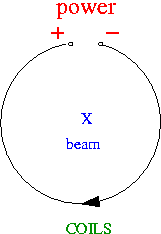
 The current direction is given by a program and is stored in the Moller
logfile for the given run. The connection hold from 1998 provides the field direction and
therefore the polarization sign of the target as follows:
     Current   Bz coils    Pz target
     +           -           +
Therefore, if the Moller asymmetry measured for +9.0A in the coils is negative,
the beam polarization in the given helicity convention is positive.
      From             To            Logical level
     summer 1998 - 30 Nov 2000             0
     01 Dec 2000 -                         1
Updated on Dec 04, 2000