The main goal of the
electronic upgrading for the Moller Polarimeter is to get
more higher bandwidth (up to 200MHz) of the detector system.
The bottleneck of the current detector electronics is PLU module type
of LeCroy-2365, that has bandwidth <75MHz. Another module
needed to
upgrading is discriminator type of Ortec-TD8000, that has input
rate
<150MHz (Pic.1).
The proposed
electronics will be built using commercially available components which
follow NIM, VME or CAMAC standards. To accomplish high single rates in
the detector subsystems, only modules capable of handling rates of
150MHz or more are acceptable.
After some searching
of the replacement candidates for these units, we founded the next
suitable
units:
| Type | Model |
Form Factor | Units | Price* |
| Programmable Logic Unit 8x8 | Caen C542 | CAMAC | 1 |
$4,550 |
| Programmable Logic Unit 8x8 | Caen V495 | VME-V430 | 1 |
$4,550 |
| General Purpose VME Board (as PLU) | Caen V1495 | VME |
1 |
$3.400 |
| Time to Digital Converter | Caen V1190B | VME | 1 |
$7.095 |
| Leading Edge Discriminator P/S 708 | P/S 708 | NIM | 2 |
$1,500 |
| Quad 300MHz Majority Logic | P/S 754 | NIM | 2 |
$1,500 |
Dual Programmable Logic Unit is 1-unit
wide CAMAC module housing 2
independent Look-Up Tables with 8 Input and 8 Output channels each.
Each Look-Up Table is realized by a 256 locations RAM that can be
addressed either via the input signals or via the CAMAC bus;the RAM
data bus can be read and written via the CAMAC bus or fed to the output
connectors.
Each section has three different working modes that can be selected
independently:
- Look-Up Table;
- Pattern Generator;
- 8 bit Input/Output Register
The maximal frequency is 200MHz in
"Normal" output mode.
Front panel connectors for input and output signals are LEMO type.
We are most interested in the "Look-Up Table" mode of this unit.
- Guaranteed 300 MHz
Operation
- Eight Totally Independent Channels
- Deadtimeless Updating Output Stage
A fifteen turn
potentiometer provides
continuous output width
adjustment from 2nSec to over 50nSec for each channel.
The threshold is variable from -10mV to -1Volt with a fifteen turn
potentiometer on each channel. Front panel connectors for input and
output signals are LEMO type.
For remotely adjustment of the thresholds and output pulse width the
discriminator
module modification is needed.
To remotely adjustment
of the output pulse width
we suppose to replace installed multi-turn potentiometer with digital
one. The most suitable candidate presented on the market today
are next:
| Type | Manufacturer |
Taps | Resistance | Interface |
| MAX5439 | Maxim Integrated Products, Inc. | 128 | 100k |
SPI |
| AD5290 | Anlog Devices | 128 | 100k |
SPI, 3-wire |
| AD7376 | Anlog Devices | 256 | 100k |
SPI |
Digital potentiometers are controlled by
using serial 3-wire or SPI
interface.
This interface can be implemented with using digital I/O board, for
example VME board type of VMICVME2510.
There is possible to place digital potentiometers inside of the module.
To do this, the connector for SPI interface should be located on the
back panel of the unit.
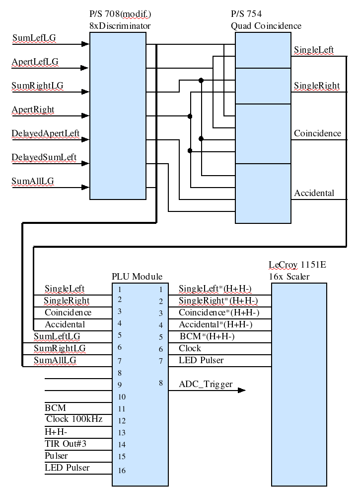
The scheme of the
detector electronics after
upgrading is shown on Pic.2.
The signals with high rate are splitting from others low rate signals.
The coincidence of these high rate signals performed on the Quad
Majority Logic Unit type of P/S 754.
The output signals from this module going to the PLU inputs.
The example of the signal connections in case of
using PLU type of
C542(V495) is shown on Pic.3.