- BC404 (for CLAS12 TOF): attentuation length 140cm(bulk 160cm), rising time 0.7ns;
- BC408 (for SoLID): attenuation length 210cm (bulk 380cm), rising time should be 0.9ns but here I used 0.7ns by mistake;
- QE: typically use 15%
- Timing:
- from these 3 references: CLAS note 91-003 (measured sigma with 200 photoelectrons); or Photonis catalog; or Hamamatsu website (datasheet):
- In
Photonis catalog, open cathode TTS (listed in sigma) includes the
center-edge difference, so the larger center-edge diff must be the full
range (I think).
-
CLAS note 91-003
catalog
PMT
rise time
TTS
rise time
TTS
Photonis XP2262
3.0ns
113ps*sqrt(200)=1.60ns
2.0 or 2.3ns
0.5ns sigma open cathode.
(0.7ns center-edge difference)
EMI 9954B05
3.3ns
101ps*sqrt(200)=1.43ns
Burle 8575
3.0ns
144ps*sqrt(200)=2.04ns
Hamamatsu R329
4.0ns
103ps*sqrt(200)=1.46ns
2.6ns
1.1ns (not sure if sigma or FWHM) XP2282B
1.5ns
0.4ns sigma open cathode (that should include the center-edge difference);
0.5ns center-edge difference (should this be the full variation then?)
Hamamatsu R2083
0.7ns
0.37ns (FWHM)
Hamamatsu R9779
1.8ns
0.25ns (FWHM)
Hamamatsu R9800
1.0ns
0.27ns (FWHM)
- Using Hamamatsu R9779 timing specifications: TTS 250ps, rising time 1.8ns, QE 15%
- An earlier CLAS TOF test (nucl-ex/0506020) which
claimed a MIP yield of 685+/- photoelectrons/4.4MeV, divided by 15% of
QE and multiplied by (3eV) of average photon energy.
- Our Preshower yield (however the preshower is a different scintillator) showed roughly 4E-3 of energy conversion.
- Some online searching, for example Table 1 in http://iopscience.iop.org/0295-5075/95/2/22001/pdf/epl_95_2_22001.pdf,
showed BC408 with 10000 photon/MeV. This is 10 times higher. However
there is no original reference from Saint-Gobain to prove this.
- Calculate nominal number of photons nph0 using 2 MeV/g/cm^2 and the scintillator thickness;
- Simulate 400 events. For each event, use Gaussian distribution to simulate the number of photons
with mean nph0 and sigma=sqrt(nph0). However, due to the large nph0
used (even for 0.5cm thickness), delta-t was observed to increase only
slightly compare to fixed nph=nph0.
- loop over all photons, following uniform solid angle
distribution, surface reflection assuming 0.99 for total internal
reflection (1% loss) and 0.95 otherwise (5% loss, Tyvek wrapping), for
attenuation using half with the first attenuation length and half with
the bulk attenuation length, calculate probability.
- Do the following for photons reaching left and right edges separately:
- When the photon reaches the readout edge, decide whether it is a successful photon by (random#)<(QE*probability)? -- note that to save CPU time can also reduce the total number of photons nph by QE, and here use only (random#)<probability.
- For successful photons, calculate the time needed to reach the readout edge, add in PMT's TTS to get the signal start time. Then, simulate the signal using a triangular pulse with rise time = (PMT rise+scintillator rise), and assuming equal rise and fall times;
- Summing all photons together, generate signal vs. time, calculate rise time (10%-90% of maximum->t1,t2; rise time=t2-t1), pulse arrival time (t1+t2)/2, and the standard deviation of the arrival time (delta-t).
- For detector with both edges readout, calculate spread in
(t_left+t_right)/2 as the timing resolution, and photoelectron
left+right as the total yield.
- If applicable, loop over 10 thicknesses from 0.5 to 5.0cm,
also loop over
20 x values (position from left to right, or from inner to outer edge
for SPD) to study the position dependence. Position uncertainty can be
added here using uniform random
distribution from -delx to +delx.
| Simulation |
PMT (TTS), TDC (resolution) used |
Comment |
|||
| Detector and size in cm |
Data and Ref | # ph.e. (center-edge) |
delta-t (c-e) |
||
| HRS S2 40(w)x60(L)x0.5(th) |
300ps (Hall A NIM) |
34-70 |
295-310ps |
Burle 8575 (2.0ns sigma, QE=25%), LeCroy 1875 (100ps) |
dominated by PMT TTS due to low nphe; PMT QE from Doug' catalog page |
| HRS S2m 14(w)x43(l)x5(th) |
100ps (S2m study?), 200ps for transversity coincidence timing, light yield about 600 (Bogdan). |
425-510 |
53ps |
XP2282B (0.4ns sigma), LeCroy 1875 (50ps) |
used light guide 0.7 efficiency to get close to 600 ph.e.; delta-t dominated by TDC |
| CLAS12 TOF test 6(w)x69(l)x6(th) |
34ps (USC note) |
650-1000 |
36-39ps |
R9779 (0.25ns FWHM); V1290N pipeline TDC (32.5ps) -- these are USC test conditions |
dominated by TDC |
| CLAS12 TOF test 6(w)x203(l)x6(th) |
51-58ps (USC note) |
230-750 |
52-81ps |
PMT TTS starts to contribute for edge events. |
|
| CLAS panel-1A TOF counter 15(w)x213(l)x5(th), BC408 |
138 ps (USC note); 118ps (1999, used XP2262) |
147-335 |
72-100ps |
don't understand why can't get USC data |
- As a reminder, we would like
- delta-t<100ps;
- number of photoelectrons >10 (original SPD
estimate, requiring preamp gain 20), >40 would allow us to use
existing PMT pre-amp with gain~5;
- signal arrival time is relevant for online coincidence timing (no position info);
- pulse rise time is required to <2.0ns.
- For SoLID offline analysis we use position from GEM, need to add that
position resolution on top of the
results below. But that uncertainty should be quite negligible if delta-x is at mm level.
- The simulation used 60ps of TDC resolution (ref: Alexandre C.)
- The simulation assumed R9779. Comparison between R9779, R9800, and fine-mesh PMT is as follows:
PMT
R9779
R9800
R5505-70 (fine-mesh, low gain)
R5924-70 (fine-mesh)
R7761-70 (fine-mesh)
XP2262
rise time (ns)
1.8
1.0
1.5
2.5
2.1
2.3
transite time (ns)
20
11
5.6
9.5
7.5
31
transit time spread TTS (ns)
0.25 (FWHM) 0.27 (FWHM) 0.35 (FWHM)
0.7 edge-center, 0.5 (??)
diameter
51mm
25mm
25mm
51mm
38mm
51mm effective area
46mm dia or 16.62 sq.cm
22mm dia or 3.80 sq.cm
17.5mm dia or 2.41 sq.cm
39mm dia or 11.95 sq.cm
27mm dia or 5.73 sq.cm
Typical gain
5E5 at 0T; 2E4 at 1T (at 0 deg, less with an angle)
1E7
1E7
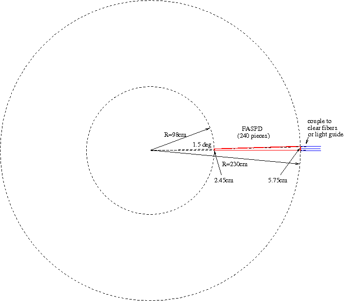
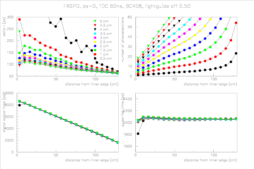
- FASPD, without position uncertainty, TDC resolution 60ns, light guide efficiency 50%, BC408
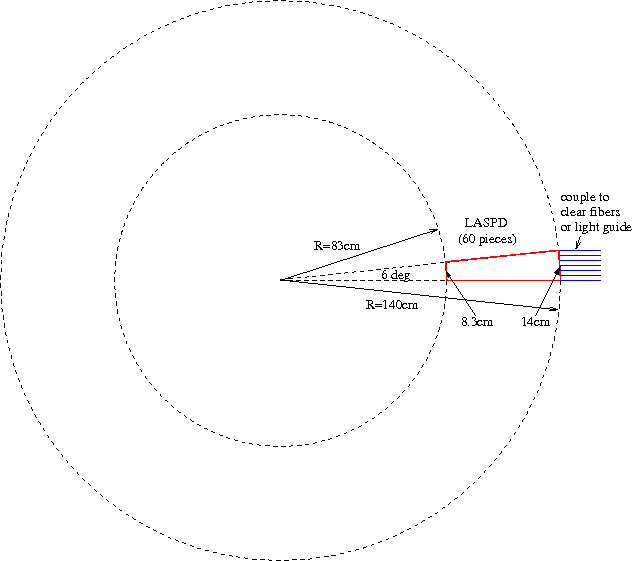
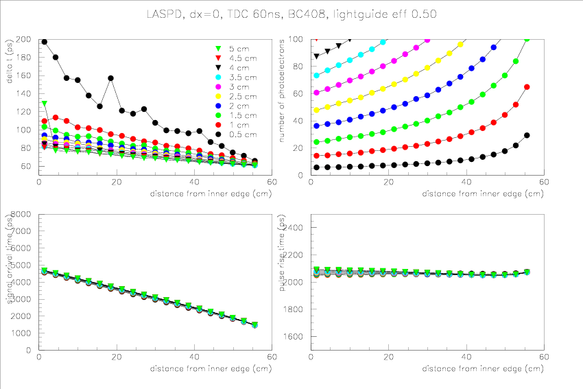
- LASPD, without position uncertainty, TDC resolution 60ns, light guide efficiency 50%, BC408
- numbre of photoelectrons is important. Large nphe minimize all
contributions to the timing spread (except for the finite position
uncertainty). This indicates the use of clear fibers (with trapping
efficiency no larger than 10%) is impossible.
- Use
of good PMT (small TTS) and TDC (small resolution) is important, since
for high light yield these two factors dominate the timing resolution. It's
also crucial we test all PMTs before using, since CLAS experience is
that the PMT spec may be 2-3 times worse than the manufacturer's values.
- For LASPD, 1cm-2cm might be okay. Depending on photon rej performance, the thicker the safer for timing resolution.
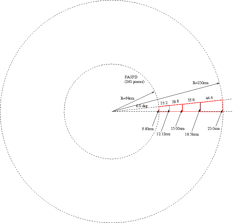
- Light yield for FASPD is a problem for inner edge, mostly
due to the length of the SPD. Based on this, for FASPD we will need to
go back to the scintillator+WLS fiber and the 4 radial+60 azimuthal
segmentation design. Here is a sketch based on equal-ratio segmentation in the radial direction.
- Prototype testing is important to pin down light output and timing.
| SDU tile size |
light output, simulated |
light output, measured |
| 10x10x0.3 |
10 p.e. |
8.2 p.e. |
| 10x10x0.5 |
20 p.e. |
48.1 p.e. |
| 10x10x1.0 |
47 p.e. |
|
| 10x10x2.0 |
106 p.e. |