1kÅ Gate Oxide SOLID STATE DOSIMETERThe Technical Data
Sheet is available in Postscript format here. 100nm
gate oxide RADFET data sheet
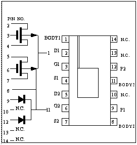
The standard chip contains two types of PMOS dosimeter, each
having different geometry,
Type 1 has a W/L value of 300/50. - PINS 1,2,3,4.
Type 2 has a W/L value of 868/11. - PINS 1,5,6,7.
(where PINS 1,2,3,4 refer to Bulk, Drain, Gate, Source ,
similarly for Type 2.)
Dosimeter operational specifcations are listed below, along with
details of device biasing for radiation sensing and threshold
voltage reading.
TECHNICAL SPECIFICATIONS
Typical values @ 27°C.
Oxide Thickness 1000Å Note: These values refer to a 300/50
device.
Sensitivity of Vth to RadiationIrradiation Field = 0.125
MV/cm : Sensitivity = 0.09mV/rad
Irradiation Field = 0 MV/cm :
Sensitivity = 0.014mV/rad
(Sensitivity at 30
krad(H2O) using a constant 10µA in Reader configuration
below.)
Temperature Compensation:TVTC 2.5mV/°C
(This figure
taken from extrapolated Vtp value in linear mode @ temps from 27°C
to 100°C.)
Z.T.C. value in Linear Mode ~ 3µA
(Vs=Vb=0, Vds=-0.1)
Z.T.C. value in Saturation Mode ~ 30µA
(Using Reader circuit
configuration below)
Pre-irradiation Dosimeter Characteristics:Threshold Voltage
(Extrapolated) -2.15 +/- 0.1V
(Also see Reader circuit graph -
Figure 2)
Vth drift with time (secs) 2.2mV/decade
(This value from
Reader configuration forcing 40µA.)
Oxide Breakdown Voltage ~ 75V
Channel Leakage Current with Vd=-12, Vg=Vs=Vbulk=0 ~ 10 pA
Subthreshold Slope 100 +/- 20 mV/decade
Channel On Resistance with Vgs-Vth=5V, Vds=-0.1 ~ 0.3 Mohms
OPERATION IN RADIATION ENVIRONMENT
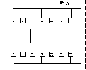
Vi = Irradiation Bias. The above biasing is used when sensing
radiation.
For low field mode; Vi=0 (all pins tied together).
For high
field mode; Vi=5V is used, giving a field of 0.5MV/cm, and Vth
change with dose is measured with the Reader circuit.
THRESHOLD VOLTAGE READER CIRCUIT
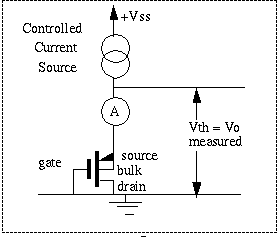
To read the total absorbed dose at any time, connect the
dosimeter in the Reader circuit above. Take Vth reading @ 20sec
after power-up. Subtract Vth(zero dose) to give the Vth shift due to
irradiation. Dose can be read from Delta Vth vs Dose graph, as in
Fig 1.
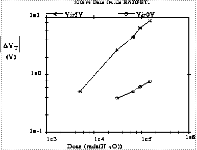
Fig 1. Radiation response of the standard 1kÅ NMRC RADFET. The
graph includes 0V and 5V irradiation bias responses.
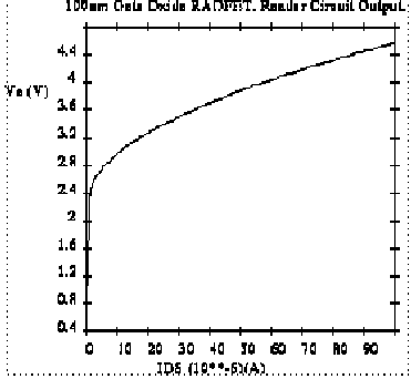
Fig 2. Vth dependence on Ids, measured using the Vo of the
Reader Circuit.
CAUTION: Devices are static sensitive. Use grounding straps when
handling packages. |