Allen Bradley's PLC Programming Handbook

This handbook is a collection of programming overviews, notes, helps, cheat sheets and whatever that can help you (and me) program an Allen Bradley PLC.
If you have experience with AB then please contribute.
An Introduction to RSLogix5000 Tags
Tags are the method for assigning and referencing memory locations in Allen Bradley Logix5000 controllers. No longer are there any physical addresses such as N7:0 or F8:7 which use symbols to describe them. These have been replaced with tags which are a pure text based addressing scheme. This is a departure from the more conventional ways of programming PLC’s, which includes Allen Bradley’s earlier line of PLC5 and SLC 500 controllers.
One of the hardest transitions from the older systems is realizing how the tag database works. The person with experience in Allen Bradley systems will recognize many of the instructions and be at home with the editor in RSLogix 5000. Understanding the tag database is the first major hurdle in becoming comfortable with the ControlLogix and CompactLogix systems. So let’s dig in and get started.
The Way We Used To Be
Earlier Allen Bradley PLCs programmed with RSLogix 5 and RSLogix 500 software had data files to store I/O and other internal values. These different data files could only hold one data type. A data type defines the format and the size of the stored value.
Default Data Files
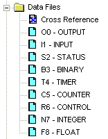
Data File Descriptions
File # |
Type |
Description |
O0 |
Output |
This file stores the state of output terminals for the controller. |
I1 |
Input |
This file stores the state of input terminals for the controller. |
S2 |
Status |
This file stores controller operation information useful for troubleshooting controller and program operation. |
B3 |
Bit |
This file stores internal relay logic. |
T4 |
Timer |
This file stores the timer accumulator and preset values and status bits. |
C5 |
Counter |
This file stores the counter accumulator and preset values and status bits. |
R6 |
Control |
This file stores the length, pointer position, and status bits for control instructions such as shift registers and sequencers. |
N7 |
Integer |
This file is used to store bit information or numeric values with a range of -32767 to 32768. |
F8 |
Floating Point |
This file stores a # with a range of 1.1754944e-38 to 3.40282347e+38. |
While this method made it easy for using instructions, it provided a challenge for logically grouping different data types together according to function. For instance, in machine control, a motor may have a start, stop, speed and alarm code each with its own data type. Thus, the data was “scattered†throughout the data files.
File # |
Name |
Data Type |
I1 |
Start |
Input |
I1 |
Stop |
Input |
F8 |
Speed Setpoint |
Floating Point |
N7 |
Alarm Code |
Integer |
Comparing the Old and New
The Logix5000 controllers have done away with data files and in its place is the tag database. The tag database organizes memory locations in one place. Each tag is assigned its own data type. The table below shows the association between the current data types and the older systems with data files.
RSLogix 5 / 500 |
RSLogix 5000 |
||
File # |
Type |
||
O0 |
Output |
Input and output modules, when configured, automatically create their own tags like Local:0:I.Data.0 |
|
I1 |
Input |
||
S2 |
Status |
Use the GSV and SSV instructions to get status information such as the CPU time, module states and scan times. |
|
B3 |
Bit |
Assign the Boolean (BOOL) data type to the tag. |
|
T4 |
Timer |
Assign the TIMER data type to the tag. |
|
C5 |
Counter |
Assign the COUNTER data type to the tag. |
|
R6 |
Control |
Assign the CONTROL data type to the tag. |
|
N7 |
Integer |
Assign the double integer (DINT) data type to the tag. |
|
F8 |
Floating Point |
Assign the REAL data type to the tag. |
|
Creating a Tag
One way to create a new tag is right click on the Controller Tags in the Controller Organizer and select New Tag. Even faster is the Ctrl+W hot key.
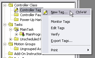
The following dialog box pops up.
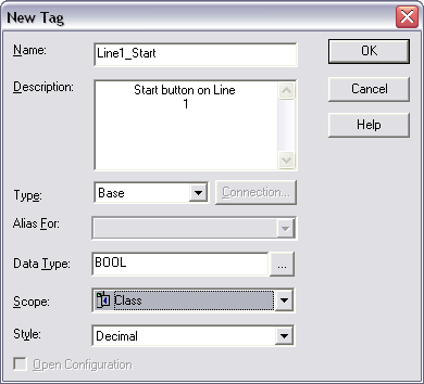
The Name given to the tag has the following rules:
- only alphabetic characters (A-Z or a-z), numeric characters (0-9), and underscores (_)
- must start with an alphabetic character or an underscore
- no more than 40 characters
- no consecutive or trailing underscore characters (_)
- not case sensitive
While tags are not case sensitive, it is good practice to mix cases for readability. It is much easier to read Line1_Start then LINE1START or line1start.
In addition, the tag database list sorts alphabetically. Therefore, it is best to use similar starting characters when you want tags to be together in the monitor list.
Tags Named for Grouping |
Tags Not Named for Grouping |
|
Level_High |
High_Level |
|
Level_Low |
Insert_Nut |
|
Insert_Nut |
Knife_Stop |
|
Knife_Stop |
Low_Level |
Use the Description field for a longer description of the tag. It is best to keep names short yet not cryptic. Tag names are downloaded and stored in the controller but the description is not as it is part of the documentation of the project.
The tag Type defines how the tag operates in the project
Base |
A tag that actually defines the memory where the data is stored |
Alias |
A tag that represents another tag |
Produced |
Send data to another controller |
Consumed |
Receive data from another controller |
Alias tags mirror the base tag to which they refer. When the base tag value changes so does the alias tag. Use aliases in the following situations:
- program logic in advance of wiring diagrams
- assign a descriptive name to an I/O device
- provide a more simple name for a complex tag
- use a descriptive name for an element of an array
Produced and consumed tags make it possible to share tags between controllers in the same rack or over a network. This article does not cover this aspect.
Select a Data Type for the tag by typing it in or by clicking on the ellipsis button and selecting it from the list. A data type is a definition of the size and layout of memory allocated for the created tag. Data types define how many bits, bytes, or words of data a tag will use.
The term Atomic Data Type refers to the most basic data types. They form the building blocks for all other data types.
Data Type |
Abbreviation |
Memory bits |
Range |
Boolean |
BOOL |
1 |
0-1 |
Short Integer |
SINT |
8 |
-128 to 127 |
Integer |
INT |
16 |
-32,768 to 32,767 |
Double Integer |
DINT |
32 |
-2,147,483,648 to 2,147,483,647 |
Real Number |
REAL |
32 |
+/-3.402823E38 to +/-1.1754944E-38 |
Logix5000 controllers are true 32-bit controllers, meaning the memory words are 32-bits wide. No matter what, a tag always reserves 32 bits of memory even if it is a Boolean or integer data type. For this reason, it is best to use a DINT when dealing with integers. Furthermore, a Logix5000 controller typically compares or manipulates values as 32-bit values (DINTs or REALs).
A Logix5000 controller lets you divide your application into multiple programs, each with its own data. The Scope of the tag defines if a tag is global (controller tags) and therefore available to all programs or local (program tags) to a select program group. Pay careful attention to this field as creating it in the wrong area may lead to some confusion later on as to its location.
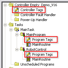
Controller Tags are available to all programs. You cannot go wrong using controller scoped tags unless you easily want to copy and paste programs. A tag must be controller scoped when used in a Message (MSG) instruction, to produce or consume data and to communicate with a PanelView terminal.
Program Tags are isolated from other programs. Routines cannot access data that is at the program scope of another program. Having program tags make it easy to copy/paste programs and not have to worry about conflicting tag names. Make sure though that no controller tags are named the same as program tags.
Style is the form in which to display the tag by default. The following table provides you with information on the base and notation used for each style.
Style |
Base |
Notation |
Binary |
2 |
2# |
Decimal |
10 |
|
Hexadecimal |
16 |
16# |
Octal |
8 |
8# |
Exponential |
0.0000000e+000 |
|
Float |
0.0 |
Edit and Monitor Tags
To edit existing tags select the Logic > Edit Tags menu item. A spread sheet like view lets you create and edit tags.
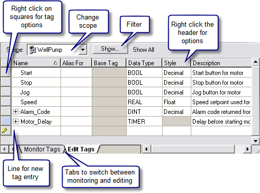
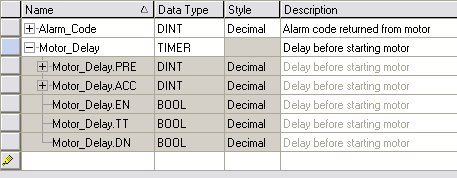
Clicking the + sign next to a tag reveals its structure. For a DINT tag this is the 32 individual bits that make up the tag which will not be of interest if you are using the tag as a number rather then individual bits. If you do wish to use the individual bits then you can address them in this way with the tag name followed by a period and then the bit position (e.g. MyTag.5). Shown below is the expanded structure for a TIMER. Notice it is made of two DINTs and three BOOLs. In this case, the Booleans are packed into one DINT and therefore a timer uses three DINTs of memory.
An Easier Way to Create Tags
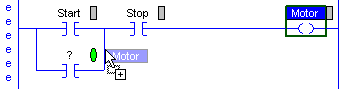
The easiest way to create tags is on the fly while programming. When an instruction is first used a “?†will indicated the need for a tag. There are three options at this point:
- Double click on the “?†and select an existing tag from the drop down box.
- Right click on the “?†and select new tag.
- Double click on the “?†and type in the tag name. If it does not all ready exist, then right click on the tag name and select Create “NewTagNameâ€. Be careful with this method not to use spaces or special characters.
The nice thing about all these methods is that RSLogix5000 will automatically fill in the correct data type according to the instruction used.
Another quick method is to drag and drop an existing tag to a new instruction. Make sure to click on the tag name rather then the instruction.
Conclusion
These are the basics of tags. The advantages are:
- Tags, if done right, create a level of documentation that is stored in the PLC.
- The software does an automatic housekeeping of memory locations. There’s no more worrying about physical addressing and memory conflicts.
- Structures can be more easily put together based on function rather then data type.
Advance subjects include arrays, user defined data types (UDT) and Add-On Instructions. Hopefully, you will continue to learn more about the power of tags. There is no doubt that if you grasp the principles presented here you will be well on your way to using and troubleshooting any Logix5000 controller.
A Quick Tutorial on RSLogix Emulator 5000
RSLogix Emulator 5000 is a software simulator for the Allen Bradley line of Logix 5000 controllers (ControlLogix®, CompactLogix®, FlexLogix®, SoftLogix5800® and DriveLogix®). The goal is to mimic the function of a PLC without the actual hardware and thus do advanced debugging. More information can be found in the AB publication LGEM5K-GR015A-EN-P.
As a quick introduction we’ll go through a simple example of setting up a simulation. This involves three major steps.
- Setting up the chassis monitor.
- Creating a connection in RSLinx.
- Creating a project with associated emulation hardware.
Setting up the Chassis Monitor
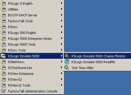
To start the Chassis Monitor, click Start > Programs > Rockwell Software > RSLogixEmulate 5000 > RSLogix Emulate 5000 Chassis Monitor.
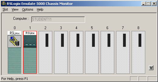
From here we set up our hardware configuration for simulation. Our first step will be to add the CPU. In this case it is a special one called an Emulation Controller.
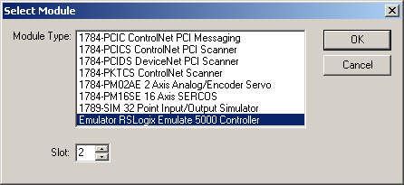
- Click Slot > Create Module.
- Choose the Emulator RSLogix Emulate 5000 Controller.
- Chose slot 2 for the controller
- Click OK to add it to the chassis monitor.
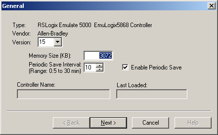
- At this point you may be accosted with a message about previous configurations. Just select Reset the Configuration to Default Values and click NEXT.
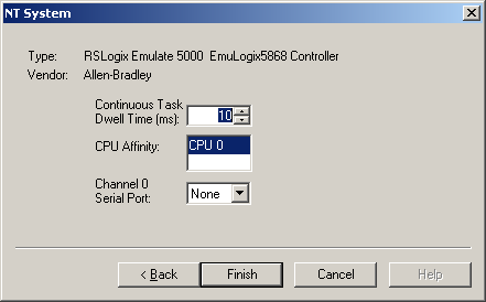
- The next two dialog screens are for setting up the controller details. Click NEXT and FINISH to accept all the defaults.
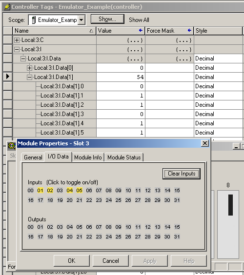
Next we’ll add some input/output simulation.
- Click Slot > Create Module.
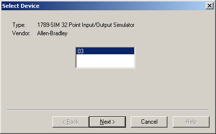
- Choose the 1789-SIM 32 Point Input/Output Simulator.
- Chose slot 3 for the simulator and click OK.
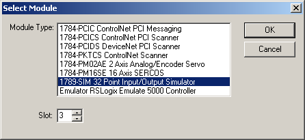
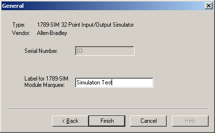
- Accept the defaults for the setup by clicking NEXT and FINISH.
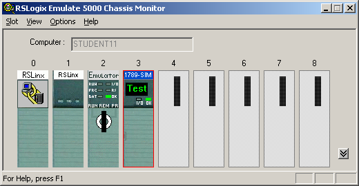
The chassis monitor will now have two emulation modules in it ready to go.
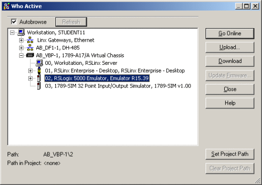
Creating a connection in RSLinx
- Start RSLinx under Start > Programs > Rockwell Software > RSLinx > RSLinx Classic
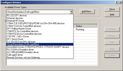
- Click Communications > Configure Drivers.
- Select the Virtual Backplane (SoftLogix 58xx) driver from the Available Driver Types list.
- Click Add New. The Add New RSLinx Driver dialog box appears. Click OK.
- The new driver appears in the Configured Drivers list. Click Close.
Using RSLogix Emulator in a Project
To use the emulator in a project you must setup the hardware correctly.
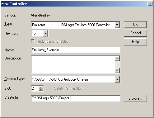
- Start the RSLogix 5000 software and create a new project.
- Under the New Controller window type select an Emulator – RSLogix Emulator 5000 Controller.
Give it a name and assign it to the same slot as the one you put in the
Chassis Monitor which in our example is slot 2. Click OK.
- In RSLogix 5000's Controller Organizer, right click on the I/O Configuration folder, and then click New Module. The software displays the Select Module window.
- Open the Other folder. Select the 1756-MODULE from the modules list and then click OK.
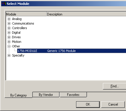
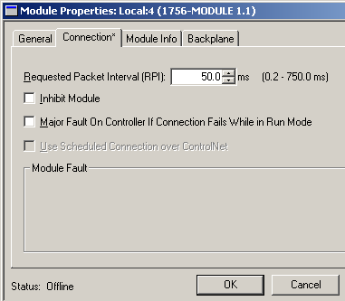
- The software displays the New Module window.
a. Add a Name for the card.
b. In the Slot field put the number that corresponds with the Chassis Monitor.
c. For the Connection Parameters put in the following and click OK
Assembly Instance Size Input 1 2 Output 2 1 Configuration 16 0 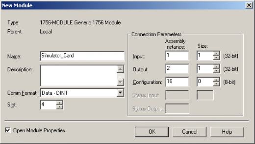
- On the next Module Properties screen make sure to change the Requested Packet Interval to 50.0 ms.
Ready, Set, Go
Getting Started with the Logix5000 PIDE Function Block
The PIDE (Enhanced PID) is an Allen Bradley Logix5000 family (ControlLogix, CompactLogix, FlexLogix, SoftLogix) function block that improves on the standard PID found in all their controllers. First impressions of this function block are quite intimidating. If you try to dive into it head first you may just end up banging your head against a wall. Many will be quite happy to stick with the tried and true PID instruction but to compete with the more advanced process control applications the PIDE boasts the following.
- It uses the velocity form of the PID algorithm. This is especially useful for adaptive gains or multiloop selection.
- Control of the instruction can be switched between Program and Operator modes.
- Better support for cascading and ratio control.
- Built in autotuner (requires extra key)
- Support for different timing modes
- More limiting and fault handling selections.
Still interested? What we want to do here is basically get you off the ground with the PIDE, distill all the options to the essentials and get it working.
The PIDE is only available as a function block (sorry, no ladder). Like the PID instruction it is best to set it up in its own periodic task. The period of the task automatically becomes the sample rate (DeltaT) of the PID loop. Just make sure when adding the new routine to the task to select the Type as "Function Block Diagram."Â
Adding the PIDE Function Block
The PIDE instruction can be added from the Instruction Toolbar under the Process tab.
Once you plop a function block onto a sheet it automatically creates a program tag for the instruction which stores all the settings. The parameters can be set or monitored by wiring input and output references or by clicking on the ellipsis box in the top right corner to reveal the block properties.Â
Opening the block properties for the PIDE instruction before RSLogix5000 version 15 meant you would be accosted with a long list of parameters.
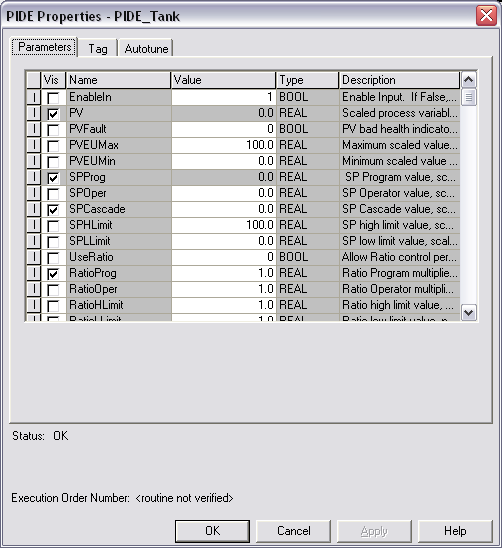
Version 15 has at least organized some of the more common settings (but not all) under tabs and groups.
Â
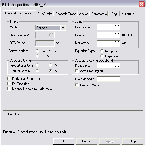
The most essential settings are:
|
Name |
V15 Location |
Description |
|
.PV |
Must be wired in from a tag. |
The Process Variable is the reading (temperature, pressure, flow, etc.) that is to be controlled by the PID loop. |
|
.PVEUMax |
EUs/Limit tab in the Engineering Units Scaling group |
The Process Variable Engineering Units Maximum and Minimum. The value of PV and SP which corresponds to 100 % span of the process variable. |
|
.SPProg |
Should be wired in or set in the tag. |
The Set Point is the theoretical perfect value of the process variable. SPProg is the value to use when in program mode and SPOper is used when in operator mode. |
|
.SPHLimit |
EUs/Limit tab in the SP Limits group |
The Set Point High Limit and Set Point Low Limit clamp the maximum and minimum values of the set point. If SPHLimit > PVEUMax or SPLLimit < PVEUMin then a fault will occur. |
|
.PGain |
General Configuration tab in the Gains group |
Proportional gain. Enter 0 to disable. |
|
.IGain |
General Configuration tab in the Gains group |
Integral gain. Enter 0 to disable. |
|
.DGain |
General Configuration tab in the Gains group |
Derivative gain. Enter 0 to disable. |
Program/Operator Control
The first thing to understand when programming a PIDE block is the different controls and modes available.Â
The Program/Operator control lets you transfer control of the PID loop between the user program and an operator interface such as an HMI. Each control has separate set points and mode controls. It's important to understand that when in Program Control the set point is determined by SPProg while in Operator Control its SPOper. The SP output indicates the set point that the function block is actually using.
Control is determined by the following inputs:
|
Name |
Description |
|
.ProgProgReq |
A program request to go to Program control. |
|
.ProgOperReq |
A program request to go to Operator control. |
|
.OperProgReq |
An operator request to go to Program control. |
|
.OperOperReq |
An operator request to go to Operator control. |
The ProgOper output indicates the control of the PIDE instruction. If the output is a 1 then it is in Program control and if the output is a 0 then it is in Operator control. The Program request inputs take precedence over the Operator requests so that the program can lock out any operator overrides. The ProgValueReset input clears all input requests.
Operating Modes
The PIDE instruction supports the following modes.
|
Mode |
Description |
|
Manual |
While in Manual mode the instruction does not compute the change in CV. The value of CV is determined by the control. If in Program control, CV = CVProg and if in Operator control, CV = CVOper. Select Manual mode using either OperManualReq or ProgManualReq. The Manual output bit is set when in Manual mode. |
|
Auto |
While in Auto mode the instruction regulates CV to maintain PV at the SP value. If in program control, SP = SPProg and if in Operator control, SP = SPOper. Select Auto mode using either OperAutoReq or ProgAutoReq. The Auto output bit is set when in Auto mode. |
|
Cascade/Ratio |
While in Cascade/Ratio mode the instruction computes the change in CV. The instruction regulates CV to maintain PV at either the SPCascade value or the SPCascade value multiplied by the Ratio value. SPCascade comes from either the CVEU of a primary PID loop for cascade control or from the "uncontrolled" flow of a ratio-controlled loop. Select Cascade/Ratio mode using either OperCasRatReq or ProgCasRatReq. The CasRat output bit is set when in Cascade/Ratio mode. |
|
Override |
While in Override mode the instruction does not compute the change in CV. CV = CVOverride, regardless of the control mode. Override mode is typically used to set a "safe state" for the PID loop. Select Override mode using ProgOverrideReq. The Override output bit is set when in Override mode. |
|
Hand |
While in Hand mode the PID algorithm does not compute the change in CV. CV = HandFB, regardless of the control mode. Hand mode is typically used to indicate that control of the final control element was taken over by a field hand/auto station. Select Hand mode using ProgHandReq. The Hand output bit is set when in Hand mode. |
If a fault occurs in the PIDE settings then it is forced into Manual mode and sets a corresponding bit in the Status words. The InstructFault output is the indicator of a fault. For more detail open the block properties and look at the Status at the bottom of the dialog box. Refer to the Logix5000 Controllers Process Control and Drives Instructions (pub 1756-RM006D-EN-P) for details.
Basic Example
Here's an example where just the essentials are used. This is a temperature control application if you hadn't guessed all ready. I've changed the look of the function block by going into the block properties, selecting the Parameters tab and checking on (or off) the boxes in the Vis column besides the inputs and outputs that are of concern.
Here's the run down on each of the inputs.
| Input | Description |
|
PV |
The process variable coming in from my TC card |
|
PVEUMax |
The span of the temperature input that equals 0 to 100%. In this case the temp goes from 0 to 1200 degC. |
|
SPHLimit |
We could limit the set point but in this test case just set it equal to the PVEUMax/Min. |
|
SPProg |
I've decided to use Program Control so the Set Point needs to come in on this input rather then SPOper. |
|
CVProg |
When in manual mode the CV is controlled by this input. |
|
DependIndepend |
I prefer the Dependent form of the PID algorithm. |
|
PGain |
The essential PID settings of Proportion, Integral and Derivative. |
|
ProgProgReq |
Set the request to use Program Control. |
|
ProgAutoReq |
Since we're in Program Control these inputs control the Auto and Manual modes. To run them off one switch the BNOT block is used to invert the bit. |
Now for the outputs.
| Output | Description |
|
CVEU |
The Control Variable output in engineering units. Every PID control needs an output. In this case it goes from 0 to 100%. |
|
SP |
The actual set point which in this case equals SPProg. |
|
ProgOper |
I want to see a 1 here just to make sure we're in Program Control |
|
Auto |
Indicates the operating mode. |
|
InstructFault |
If I screw something up then this bit will come on. |
Common Problems
|
No output |
|
|
Output is limited at 100 |
|
Conclusion
Hopefully this basic introduction has gotten you off the ground. Half the battle is just getting it to work. Once that is done you can now really start to tinker with the power of the PIDE function block.
Further Reference
- Logix5000 Controllers Process Control and Drives Instructions (Publication 1756-RM006D-EN-P)
- Using the PIDE Instruction (Publication LOGIX-WP008A-EN-PÂ - August 2005)
- Using a Logix Controller for Barrel Temperature Control on Plastic Injection Molding and Extruding Machines (Publication RA-AP015A-EN-P €“ February, 2004)
Install and Test a MVI46-MCM Modbus Module for SLC-500
by Nugroho Budi from controlmanuals.com
The MVI46-MCM is a Modbus communication module provided by ProSoft Technology. The module can be installed in a SLC500 rack so it can communicate to other Modbus devices.
This article assumes you have an Allen Bradley SLC 5/03, 5/04, or 5/05 processor with a power supply of adequate capacity for the MVI46-MCM plus any Input/Output (I/O) modules you intend to use. For the purposes of this lab, and to match the supplied sample ladder, we will assume a configuration as follows:
- A-B 1747-L551 5/05Processor – 16K Memory, OS500
- A-B 1746-A7 7-Slot Chassis (rack)
- A-B 1746-P1/P7 Power Supply
If different hardware is used, modifications to the sample ladder file, MVI46MCM.RSS will need to be made to obtain a properly functioning program.
Installing the Module
- Before installing the MVI46-MCM into the SLC chassis, check the
position of the Interface Configuration Jumpers on the bottom of the
module.
The Setup Jumper is only necessary when used to flash a firmware upgrade onto the module. For normal configuration and operation, this jumper must be positioned as shown in the diagram above. We will be using the RS-232 interface, so check that the PRT2 and PRT3 jumpers are positioned as shown above so the module will communicate in RS-232 mode. - NOTE: For this step, and at any time when you are
installing or removing hardware to or from the chassis, you MUST do so
with the POWER OFF! SLC modules are NOT HOT SWAPABLE.Â
Attempting to insert or remove modules while the chassis is powered-up
can result in damage to the module, the processor, the Power Supply,
and/or the Chassis itself!
Chassis slots are numbered sequentially, left to right, starting at zero for the leftmost slot. The processor always goes in Slot 0. Install the MVI46-MCM module into the slot next to the processor. This will place the module in Slot 1. The rest of the chassis slots should be left empty, for now. If done correctly, your installation should look similar to the following illustration:
- Set the processor key switch to the REM position and power up the chassis.
After its boot cycle, the processor will be ready to accept programming. At this point, you may ignore any RED LEDs indicating processor or module faults. Until a valid project (program) is loaded into the processor it may show a fault.
Configure RSLinx to Talk to SLC
- Attach a null modem cable (or the A-B CP3 programming cable) from your PC serial port to the serial port on your SLC processor, called Channel 0.
- Open RSLinx. Click on the “Communications†drop-down
menu. Click on the “Configure Drivers†option. If
you’re running a newer version of RSLinx, you’ll see a dialog box
like this one:
If you already have a RS-232 DF-1 driver configured, skip to the Auto Configure instructions in Step 5. - Click the down arrow in the “Available Driver Types:†option box
and click on “RS-232 DF-1 devicesâ€, as shown, and click the “Add
New…†button.
- You will now be prompted to name your driver. For most cases,
the default name will be acceptable. To match the sample project
used in this lab, accept the default name by clicking the “OKâ€
button.
- Next, you will see the driver setup dialog box.
- First, click the down arrow in the “Comm Port:†option box and click the Comm port that matches the number on your PC (usually Comm1, Comm2, Comm3, or Comm4).Â
- Then, click the down arrow in the “Devices:†option box and click the “SLC-CH0/Micro/PanelView†option.Â
- Finally, click the “Auto Configure†button. RSLinx will
then query the processor, establish a communications link, and adjust
the driver’s parameters to match the processor’s current port
configuration. Don’t worry if the parameters in your driver
don’t match the ones shown in the following example. As long as
the window reports “Auto Configuration Successful!â€, whatever
parameters appear for baud rate, parity, error checking, etc. will be
correct. A successful result will look something like this:
In some instances, RSLinx will fail to Auto Configure. If this happens to you, first check that your cable is OK, properly connected, and that you are selecting the correct Comm port. Once this is verified, if Auto Configure fails, you will need to completely wipe the processor memory and reset it to factory defaults. Consult the A-B product documentation, the A-B website, or A-B Tech Support for instruction on how to do this. Once done, the RSLinx should be able to Auto Configure.
Clicking on “OK†will return you to this dialog:
Â
If the driver status is “Runningâ€, you have now successfully configured RSLinx to talk to the processor. Click the “Close†button to close this dialog and then exit but do not shutdown RSLinx by clicking the “File†menu option and then “Exit and Shutdownâ€. Be sure to click the “Exit†option.
Use RSLogix500 to Modify the Sample Project
- Next, we will load and configure the sample ladder logic program and
download it to the processor. Start RSLogix500. It should
come up to a blank window, like this:
- Click on the “File†drop-down menu, click “Open†and browse
to the folder where you saved the sample ladder and double-click the
file, “MVI46MCM.RSS†that is included on the MVI46MCM CD.
This will open the sample project. We can now configure the sample ladder to get it ready for the next exercise. - You’ll get a window that looks like this. If not, then
click on the “View†Menu, and make sure there are check marks beside
“Standardâ€, “Onlineâ€, and “Tabbed Instruction Bar†options.
- In the left pane Project Tree area, under the Controller folder,
double-click on the “IO Configuration†icon. This will
display the I/O Configuration dialog box:
- Click on “OTHER†in Slot 1, as shown, then click the “Adv Config†button.

Make sure the values are as shown. If they are not, set them to these values. Otherwise, the module will not function properly. Details on module setup are contained in the User’s Manual in Section 3.3 “Setting Up the Moduleâ€. After you verify the values, click “OK†or “Cancel†to close this dialog box. Click on the Exit icon ( ) in the upper-right corner of the I/O Configuration dialog to close it and return to the main window.
 - In the left pane Project Tree area, under the Data Files folder,
double-click on the N10 – MCM CFG icon. Set the values in this
file to match the ones shown below.
MCM Ports 1 & 2 Cmds Port 1 / Port 2 - N10:10 / N10:40Â Port Enable/Disable - N10:11 / N10:41Â Port Type - N10:12 / N10:42Â Float Flag - N10:13 / N10:43Â Float Start - N10:14 / N10:44Â Float Offset - N10:15 / N10:45Â Protocol - N10:16 / N10:46Â Baud Rate - N10:17 / N10:47Â Parity - N10:18 / N10:48Â Data Bits - N10:19 / N10:49Â Stop Bits - N10:20 / N10:50Â RTS On Delay - N10:21 / N10:51Â RTS Off Delay - N10:22 / N10:52Â Min. Response Delay - N10:23 / N10:53Â Use CTS Line - N10:24 / N10:54Â Slave ID - N10:25 / N10:55Â Bit Input Offset - N10:26 / N10:56Â Word Input Offset - N10:27 / N10:57Â Output Offset - N10:28 / N10:58Â Holding Register Offset - N10:29 / N10:59Â Command Count - N10:30 / N10:60Â Min. Command Delay - N10:31 / N10:61Â Command Error Pointer - N10:32 / N10:62Â Response Timeout - N10:33 / N10:63Â Retry Count - N10:34 / N10:64Â Error Delay Count - N10:35 / N10:65Â Reserved - N10:36 / N10:66Â Guard Band - N10:37 / N10:67Â Guard Band Timeout
This configuration data will set module Port1 to be a Modbus Master and Port2 to be a Modbus Slave. Both ports will be set for Modbus RTU mode, 57,600-baud, no parity, 8 data bits, 1 stop bit. Hardware handshaking will be disabled (RTS/CTS not used.) We will be able to use up to 5 Modbus Commands and any Modbus Command Errors will be sent to module memory beginning at register address 300, which will then appear in SLC data table N31, beginning at N31:100. With this configuration, we can use a second null modem
cable and two DB9M-to-RJ45 pigtails to connect the two ports together, which in turn will allow us to send and get data from the module with our sample ladder. Click on the Exit icon () in the upper-right corner of the Data File N10(dec) dialog to close it and return to the main window. - We will now configure our Modbus commands for Port1. In the
left pane Project Tree area, under the Data Files folder, double-click
on the N11 – P1 CMDS icon. Set the values in this file to match
the ones shown below.
MCM Ports 1 & 2 Cmds Port 1 / Port 2 - N11:0 / N12:0Â Cmd Enable - N11:1 / N12:1Â Internal Address - N11:2 / N12:2Â Poll Interval Time - N11:3 / N12:3Â Count - N11:4 / N12:4Â Swap Code - N11:5 / N12:5Â Node Address Device ID - N11:6 / N12:6Â Function Code - N11:7 / N12:7Â Device Address Register
This creates one Modbus command for Port1, our Master port. This command will send a request out Port1 to the Modbus Slave at Slave ID 2 (our Port2), as configured in N10. The command will get twenty 16-bit words (registers) of data from Destination Address 0, our module address 0, the first word of our WRITE DATA area, and move it out Port2, in Port1, and store it in Internal Address 200, our module address 200, the first word of our READ DATA area. This command will execute once each second.  This way, any values we poke into data table addresses N32:0 through N32:19 will, after a short delay, appear in the corresponding addresses in data table N31. Click on the Exit icon () in the upper-right corner of the Data File N11 (dec) dialog to close it and return to the main window. - In the left pane Project Tree area, under the Data Files folder,
double-click on the N12 – P2 CMDS icon. Set all the values in
this file to zero and click on the Exit icon () in the upper-right corner to close this window and return.
- In the left pane Project Tree area, under the Data Files folder,
double-click on the N32 – WRITE DATA icon. Set the values in
this file as shown.
This will give us some beginning data values for the Modbus command we just created. Click on the Exit icon () it the upper-right corner to close this window and return. - In the left pane Project Tree area, under the Data Files folder,
double-click on the N31 – READ DATA icon. Set the values in this
file to zero so that we will know that any values that appear there are
the result of our ladder logic execution. Click on the Exit icon
() in the upper-right corner to close this window and return.
- We are now ready to save our new project before downloading.Â
In the main window, click on “Fileâ€, then “Save As†to get the
Save As dialog box. In the File Name: box, type “46Test1â€, as
shown, and click the Save button.
Congratulations! You now have a functioning program that will move data to and from the module.
Downloading and Testing the Modified Sample Project
- Make sure your null modem cable (or CP3 programming cable) is still
attached between your PC Comm port and the processor RS-232 port.Â
Take the two DB9M-to-RJ45 pigtails and the other null modem cable and
connect the lower two ports on the MVI46MCM module,
P2 APPLICATION and P3 APPLICATION, with these cables. - Set the processor key switch to the “PROG†position. In
RSLogix500, click the down-arrow next to the “OFFLINE†status and
click “Download…†from the menu.
When you see the confirmation dialog, click the “Yes†button.
The sample ladder is currently configured for a 1747-L551 SLC 5/05. If you are using a different processor, when you try to download, you will see the following:
If you get this warning screen, click the “OK†button. RSLogix will automatically determine the actual processor type you are using and adjust the IO Configuration to match your installed processor. You should then see the following window:
When it comes up, make sure the “Clear I/O†box is NOT checked, as shown, and click “OKâ€. A Download Progress dialog will flash through several progress bars as various parts of the program are loaded. Eventually, you should see:
Click the “Yes†button. The RSLogix status box will change to show you are on-line live with the processor. You can also tell you are on-line when you see the colored blocks and ladder rotating in the status box. The faster they rotate, the higher your connection speed. It should look like this (with animated ladder):
If you had to change your processor type, now would be a good time to re-save the program. - Next, we will change the SLC 500 processor key switch from
“PROG†to “RUN†and back to the “REM†position. If
you have a good program, the processor RUN LED will light up solid green
and, on the MVI46MCM module, the OK LED will change from red to green,
the APP STATUS and BP ACT LEDs will be amber and the LEDs for P2 and P3
will flash green about once every second. The RSLogix status box
should look like this:
If, however, the processor “FAULT†LED flashes red and you see this,
it indicates some kind of hardware or software problem. Common causes include: hardware failure, ladder logic errors, and installing the MVI46MCM module in a different chassis slot than the one selected in the I/O Configuration, I/O modules in the configuration that are not actually installed in the chassis, and more. Assuming you are still on-line with the processor, to see what might be causing the problem, you can check the “Processor Status†dialog for the Major Error Code causing the fault. In the Project Tree, under the
“Controller†folder, click on “Processor Status†then click on the “Errors†tab to see the fault. An example of having the module in the wrong slot is shown. Your error may be different.
Do whatever is required to fix the root cause of the fault and then turn the key switch from “REM†to “PROG†to “RUN†and back to “REM†to get the processor running normally. - NOW…We’re ready for some real fun. Take a few minutes to
look at the three LAD files in our test program. For a detailed
explanation of what these files do, look at Chapter 4 – Ladder Logic
in the User’s Manual, beginning on page 25.
Now, look in LAD 4 –MCM CMDS at rungs 0002 and 0003. Bit B3:0/0 in rung 0002 is called the Cold Boot bit. Bit B3:0/1 in rung 0003 is called the Warm Boot bit. Either may be toggled to force the module to restart, reload its configuration and any Modbus commands. This is a handy feature that makes it easy to change and test different configurations and commands. It’s quicker and safer to toggle these bits than to recycle the processor or power-down and power-up the chassis to accomplish the same thing. Toggling either of these bits allows configuration and command changes to be performed without halting the processor. This can be very useful when added one of our modules to an existing application already in use at a customer site. As we progress through the rest of this exercise, we will be returning to this ladder and these rungs often as we modify and test our program.
Toggle one of these bits now and watch the LEDs on the front of the module as you do so. You should see the P2 and P3 LEDs stop the regular blinking they had been doing, the OK LED will briefly turn red then go back to green, and then the P2 and P3 LEDs should resume their blinking once a second.
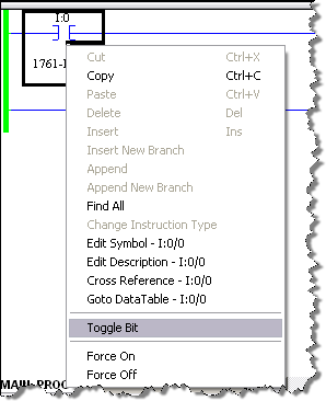
To toggle the bit, right-click on its picture then click on “Toggle Bit†at the bottom of the context menu, as shown. Be sure to watch the face of the MVI46-MCM module as you click.
- Now we can check to be sure our program is moving the data as it
should. Remember previously that we zeroed out our READ DATA
table and put test values in our WRITE DATA table. If our program
is working correctly, we should now have the same values in the same
relative addresses in our READ DATA as in the WRITE DATA. First,
let’s check the WRITE DATA table to be sure our test values are still
there. In the Project Tree, under the Data Files folder,
double-click “N32 – WRITE DATAâ€.
Yep! Our test data is still there, just the way we left it. Now, for the moment of truth…does our N31 – READ DATA table look the same? - Double-click on “N31 – READ DATA†and let’s see. If
your tables overlap each other, you can click-and-hold on the blue Title
Bar of either one, drag it to a different position in the window, and
release. Ready, GO!
YES!!!!! They MATCH! Now, that was easy, wasn’t it? You can experiment further with the above by changing the values in Data File 32, N32:0 through N32:19. With the PLC in Run Mode the values in Date File 31, N31:0 through N31:19 should, after a very short delay match those in Data File 32.
Using ModScan to simulate the Modbus Master
- Using Windows File Explorer, go to the CD and expand the yellow
folder in the left side tree pane titled Utilities under the InRAx
folder until you see a folder titled Modscan.
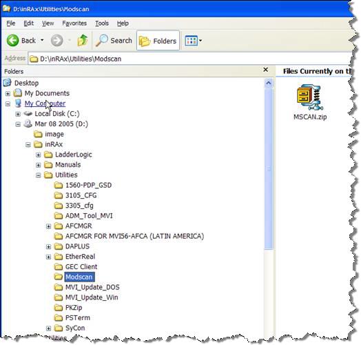
- Double-click on the compressed folder in the right side Explorer pane to extract its contents. Choose or create a new folder to contain these files. A suggestion would be to create a new folder titled Modscan, and then extract the compressed files into this new folder.
- After extracting the Modscan files, locate and double-click on the
file titled Modscan.exe. You should see the following program
appear.
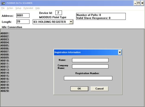
- This is the Windows program called Modscan. This is a shareware program and can be used for 30 days, after which you are asked to purchase it.
- To use the program, click either Cancel or OK to close out the “Registration Information†dialog window. You may have to click once inside the window, and then click OK. Repeat if necessary. Now we are ready to use the program.
- Remove the short RJ45 pigtail cable from Port 1 on the MVI46-MCM and
then disconnect it from the RS232 Null Modem cable. Now connect
the RS232 Null Modem cable directly to the COM 1 port on your
computer. If you currently have another cable connected to
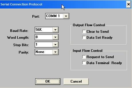
your computer’s COM 1 port for interfacing to the SLC-500, first go offline with RSLogix 500 software, then disconnect that cable and connect the RS232 Null Modem cable that was previously connected to Port 1 of the MVI46-MCM module. We should now have COM1 on our PC connected with a RS232 Null Modem cable directly to Port 2 on our MVI46-MCM module which is configured as a Modbus Slave device. - In the Modscan program, click on the menu choice called “Setupâ€,
and then click on Serial. Configure the settings as shown below.
Click OK when done.
- Now click Setup, then Display and make sure that Data and Decimal have check marks beside them. Click on Setup, then Protocol and make sure RTU is checked also.
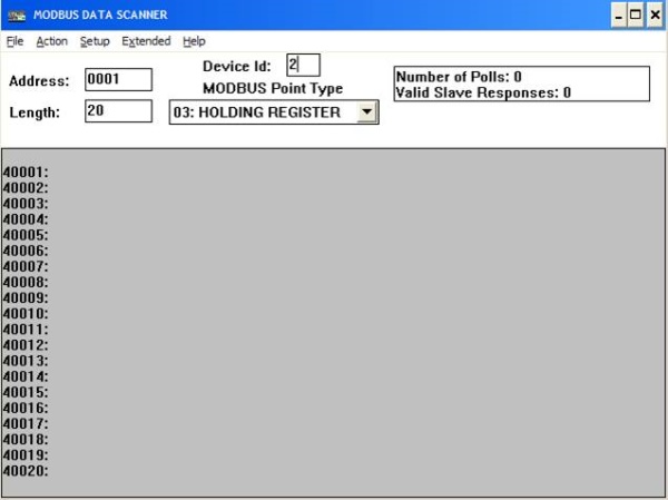
- Now configure the main window as below.
- Now click on the menu item “Actionâ€, then Start Poll. You
may have to clear a popup window first, but you should see results like
below which shows our original data that was in our Data File 32.
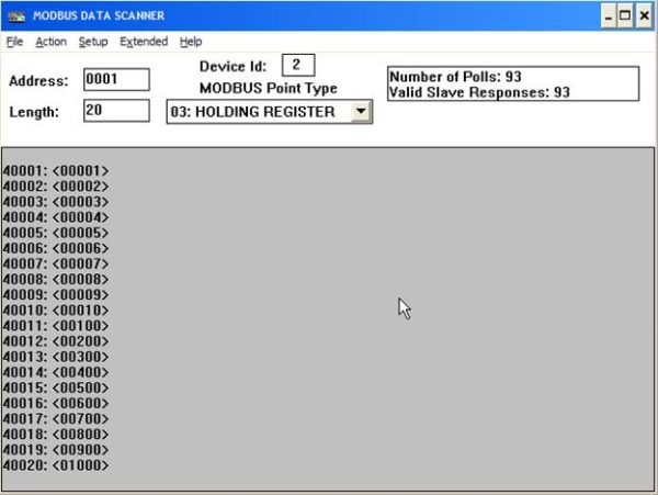
The register addresses are on the left and listed 40001 through 40020 and each registers value is directly to the right of it.
Congratulations, you have just used a Windows software program called Modscan acting as a Modbus Master device to go out and read data from our MVI46-MCM module’s Port 2 which is a Modbus Slave device.
NOTE : Based on my experience the MVIMCM for SLC500 is unable to be a Slave and must be A MASTERÂ to communicate with other Modbus PLC/Devices (Scadapack32, Micromotion, UltraSonic Flow Meter GM868..)
Learn Ladder Logic with a Free Version of RSLogix 500 and RSEmulator 500
One of my most common questions is, “Where can I get a free download of RSLogix 500?â€Â For any serious development with SLC500 or MicroLogix there is no free option but there is a nice free option if you only want to learn and/or program a MicroLogix 1000 or 1100. Programming a MicroLogix is very very similar to programming a SLC500 or in that case a PLC5 too.Â
Allen Bradley offers as a free download a software package called RSLogix Micro Starter Lite which is essentially the same programming environment as RSLogix 500. On top of that, they also offer RSLogix Emulate for free so that you don’t even need a PLC to run and test your ladder logic. Keep reading and I’ll show you how to get the software and set it up.
Getting the Software
The RSLogix Micro Starter Lite software is only available as a download at http://www.ab.com/programmablecontrol/plc/micrologix/downloads.html. If you are starting from scratch and do not have the RSLinx software then download the kit bundled with RSLinx Classic Lite. FYI, I find it a bit confusing but they also sell software called RSLogix Micro Starter which supports the full MicroLogix range.
If you do not have a MicroLogix 1000 or 1100 to play with then download the RSLogix Emulate 500 software. You’ll be able to use this to simulate a real PLC.
Note for Windows XP users: The bundled version of RSLinx only installs on Windows Pro and is not supported on Windows XP Home versions. To get around this I downloaded an older version of RSLinx Lite 2.50 from the Allen Bradley software update page http://www.rockwellautomation.com/support/webupdates/
Once you’ve downloaded the software and extracted it then install RSLogix Micro followed by the RSLinx Classic Lite software. Next, install the RSLogix Emulate 500 software.
First Steps with RSLinx
RSLinx is the software RSLogix will use to communicate with your PLC or in our case to the emulator.
Let’s start by running the RSLinx software under the START > All Programs > Rockwell Software > RSLinx > RSLinx Classic shortcut. Follow these steps to set it up:
- Under the Communications menu select Configure Drivers. Â Â
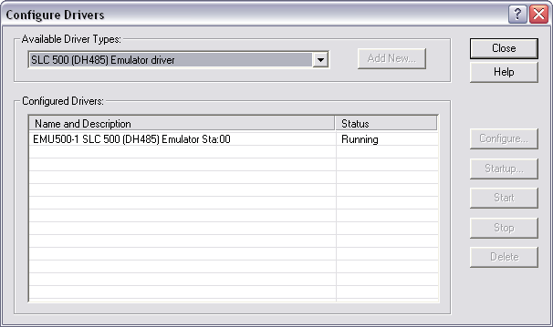
- Under the Available Drivers Types select the “SLC 500 (DH485) Emulator driver†and click the Add New… button.Â
- You can give the driver a name but I just leave it at the default of EMU500-1.Â
- Leave the configuration options as Station Number 00 and click OK.
Your driver should now be running and look like the picture below.
Ok, that’s ready to go. Close the Configure Drivers dialog box and close RSLinx. Actually RSLinx is now running in the background and you’ll probably see its little icon in the system tray.
RSLogix Micro Starter Lite
Now for the moment we’ve all been waiting for--- creating some ladder logic. Open the RSLogix Micro software with the START > All Programs > Rockwell Software > RSLogix Micro English > RSLogix Micro English shortcut. Create a brand new project by pulling down the File menu and selecting New. Every project must start with a designated processor.Â
In my case I’ve chosen the simplest MicroLogix 1000 and then clicked the OK button. FYI, if you ever work with the purchased version of RSLogix 500 then there will be a lot more items in this hardware list. A blank project now opens up.
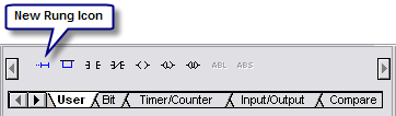
Let’s make a simple rung to test in our emulator. Make sure the cursor is on the rung with the END on it and then click the New Rung icon in the instruction toolbar.
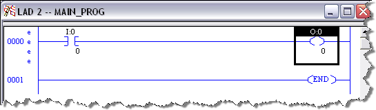
Now click on the “Examine if Closed†![]()  instruction
to add it to the rung. Double click on the question mark above
it and enter I:0/0 as its input address. Just leave the
description pop up box empty by clicking OK.
 instruction
to add it to the rung. Double click on the question mark above
it and enter I:0/0 as its input address. Just leave the
description pop up box empty by clicking OK.
Next, click on the Output Energize ![]() Â instruction
to add it to the right side of the rung. Double click on the
question mark above it and enter O:0/0 as its output address.
 Just leave the description pop up box empty by clicking OK.
 instruction
to add it to the right side of the rung. Double click on the
question mark above it and enter O:0/0 as its output address.
 Just leave the description pop up box empty by clicking OK.
You should now have something like below.
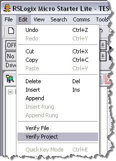
The next very important step is to verify the project with the Edit > Verify Project menu item. This will compile the project and get it ready for the emulator.
Save the project as something like Test.RSS in an easy place to find like My Documents.
RSEmulator 500
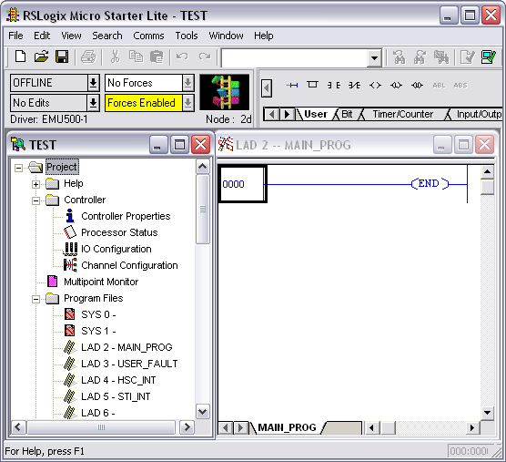
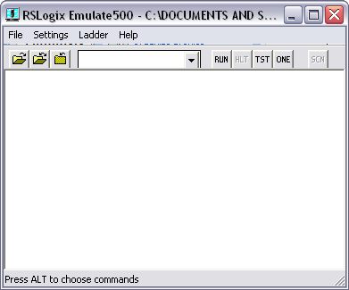
The emulator lets us test our work by running a virtual PLC. We’ll be able to download our program to it and run it in a very similar fashion to a real PLC. Start the emulator with the START > All Programs > Rockwell Software > RSLogix Emulate 500 > RSLogix Emulate 500 shortcut.  The emulator is pictured below. I know. It doesn’t look like much but it gets the job done.
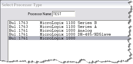
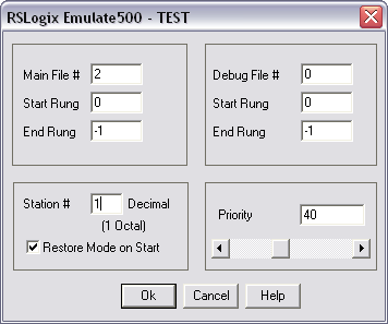
Select File > Open and open the RSLogix project you created earlier (I named mine TEST.RSS). In the dialog box that pops up put the Station # as 1 and click Ok.
Believe it or not but the emulator is now ready. Leave it running and go back to your project in RSLogix Micro.
Testing the Ladder Logic
In RSLogix Micro Starter select the Comms > System Comms menu item. The following dialog box will pop up.
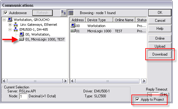
In the left hand pane, drill down and select the “01, MicroLogix 1000, TEST†processor. Yours might look a little different if you selected different hardware or gave the processor a different name. For good measure make sure Apply to Project is checked and then click on Download. When prompted to go Online click on Yes.
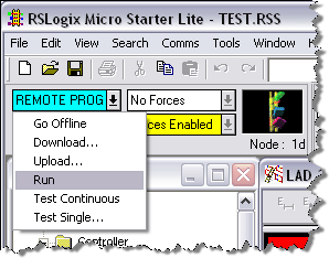
If successful you’ll see the ladder picture spinning round on the online toolbar. To scan the ladder logic put the processor into Run mode by clicking on the arrow to the right of mode status (REMOTE PROGRAM).
To test the ladder logic, change the input state by right clicking on the address and selecting toggle bit.
You will see the instruction go green indicating it is true and it will make the output instruction turn green also indicating the output is turned on.
That’s it! You get all that for the cost of a download. Now break out the manuals and start learning about all the different instructions.
RSLogix 5000 Tips and Tricks
Everybody enjoys nifty little tips and tricks to get their work done faster. This listing is for Allen Bradley's RSLogix 5000 software. Feel free to add your own tips and tricks using the 'add comment' link.
General
- To access Release Notes for this version of software, choose Release Notes from the Help menu.
- The Quick View Pane, located below the Controller Organizer, provides "thumbnail" information for the selected component.
- The Watch Pane, located below the language editor window, provides monitoring for all tags referenced in the active routine window.
- The Controller Organizer is dockable. That is, you can drag it to the left or right side of the screen, or float it somewhere in between.
- Hide/show the Controller Organizer via a toolbar button to make more display area for editors.
- RSLogix 5000 supports Cut/Copy/Paste/Drag/Drop of components within the Controller Organizer as well as to other instances of RSLogix 5000.
- Double-clicking on error messages displayed in the Error Window will navigate you to where the error was encountered.F4 and Shift-F4 can be used to move between errors.
- You can reorder the columns in the tag editor by clicking on the title and dragging it to a new position.
- To simultaneously display logic in multiple routines, select Window -> New Window and then arrange the windows manually. Or select Window -> Tile Horizontal.
- To remove a yellow triangle warning symbol on a device, first check the connection status. If the status is "Connection is not scheduled", re-open the RSNetWorx software. Return to RSLogix 5000 software and the yellow triangle should be gone.
- On one computer, you can install and simultaneously launch (run) multiple translated versions of RSLogix 5000 software.
- Once you do a partial import of rungs, add-on instructions, or user-defined data types, you can't undo the import. If the import didn't work as expected, close the project without saving.
- When you select a partial import, make sure to select the correct rung or trend file. Both files have L5X extensions and the software doesn't prevent you from selecting the wrong file. If you try to import a rung where a trend is expected, or vice versa, the software does display an error that the import failed.
- Partial import of rungs works in all ladder routines, including Add-On Instructions.
- In version 15, the Tag Editor added support for New Window.
- To simultaneously display logic in multiple routines, select Window -> New Window and then arrange the windows manually. Or select Window -> Tile Horizontal.
Keyboard
- Keyboard shortcuts are listed in the Online Help, under the "Navigating the Software" topic.
- You can use Ctrl+Page Down and Ctrl+Page Up to move between tabs in a dialog or routine window.
- You can use Ctrl+Tab and Shift+Ctrl+Tab to move between multiple RSLogix 5000 views.
- You can use Ctrl+G to invoke the Go To dialog. The Go To dialog is convenient for navigating the software.
- You can use Alt+Insert to open the Language Element browser in any of the language editors. You can also invoke this browser by pressing the Insert key in the LD, SFC and FBD editors.
- You can use Ctrl+Space to invoke the Tag browser from within the ST editor.
- You can use the Go To dialog (Ctrl+G) to quickly navigate to routines called by the current routine and to routines that call the current routine.
- In the Sequential Function Chart Editor, you can use the Routine Overview (Ctrl+B) tool to view your entire SFC and help navigate to a specific area of your chart.
- Double-clicking on error messages displayed in the Error Window will navigate you to where the error was encountered. F4 and Shift-F4 can be used to move between errors.
- The Language Element browser is a shortcut to adding logic. In the any of the language editors: use Alt+Insert, type the instruction mnemonic, and press Enter. You can also invoke this browser by pressing the Insert key in the LD, SFC and FBD editors. This short cut can be much quicker than using the instruction toolbar.
- As you use the keyboard to move the cursor around grid cells, press Alt+Down arrow to activate any controls that are active for that cell. This works in all grid-based editors, such as the Tag Editor, Data Monitor, etc. This gives you a way to access cell controls via the keyboard, rather than using the mouse.
Controller Projects
- Whenever you go online using RSLogix 5000, changes made to controller are simultaneously made to a temporary copy of the project file (.ACD). Save makes these changes permanent. Therefore, an upload is only necessary to obtain the latest copy of the tag data in the controller.
- Both Rockwell Automation and third-party sample projects are installed with RSLogix 5000. You can find them in the RSLogix 5000 Samples folder. These projects demonstrate program techniques and code that you can use to program select modules.
- Avoid pointing one alias tag to another alias tag to ensure the application maintains the appropriate references after an upload.
- Avoid pointing multiple alias tags to the same base tag to ensure the application maintains the appropriate references after an upload.
- All tag names are downloaded and resident in the controller along with your logic.
- On download, if the ControlNet schedule stored in the offline RSLogix 5000 project file is old, RSLogix 5000 will retrieve the latest ControlNet schedule from the associated RSNetWorx project file. To make an association to an RSNetWorx project file, use the RSNetWorx tab in the Module Properties dialog of the ControlNet scanner.
- RSLogix 5000 supports moving your project from one Logix platform/controller to another.
- ACD, L5K, CSV, and L5X files are independent of which translated version of RSLogix 5000 imports or exports the file. The software doesn't create language-specific import/export files.
- Use any translated version of RSLogix 5000 software to go online to a controller without having to re-download.
- In a safety controller, standard tags in a safety mapped relationship follow safety restricted states. For example, a standard tag mapped to a safety tag is read-only in a safety locked state.
- Use Add-On Instructions to initialize tag values to specific values at the beginning of each routine or program scan. Then source protect the AOI to assure that values are correctly initialized and not overwritten manually.
- The order of members within a User-Defined Data Type affect the memory size of the data type. Within the UDT, keep members of the same data type together.
I/O Configuration
- Module icons in the I/O Configuration folder change to indicate the module has faulted or the connection to the module has been interrupted.
- To remove a yellow triangle warning symbol, first check the connection status. If the status is "Connection is not scheduled", re-open the RSNetWorx software. Return to RSLogix 5000 software and the yellow triangle should be gone.
- To easily find a module in the Select Module Type dialog, simply start typing any part of the module name or description. When you start typing, the Find Module dialog is launched automatically.
- Use rack optimized communication formats for digital I/O modules to minimize amount of controller memory and communications overhead associated with these modules.
- RSLogix 5000 automatically creates controller tags when you create an input or output module. You can reference these tags directly in your logic.
- Use alias tags to assign names to specific input/output data and/or to provide a short alternative to lengthy structure member names.
- When you configure an analog I/O module, hold the shift key as you move the slider to increment HH, H, L, and LL values in whole numbers.
- Copy I/O data to a User-Defined Type (UDT) so you can synchronize I/O data with program scan. The UDT also enables easier mapping of physical I/O.
Tasks, Programs and Equipment Phases
- An event task in Logix is similar to the processor input interrupt (PII) in the PLC-5. Multiple event tasks can exist in the controller, each configured to execute at the initiation of independent triggers.
- A periodic task in Logix is similar to the selectable timed interrupt (STI) in the PLC-5. Multiple periodic tasks can exist in the controller, each configured to execute at independent rates.
- Double-click on a state in an Equipment Phase to navigate to the logic for that state.
- Use RSBizWare Batch software to create Equipment Phases. Use the Equipment Editor to create the phases, define parameters, and synchronize the phases with an RSLogix 5000 project.
- Use any programming language (Ladder, Structured Text, FBD, or SFC) to program state routines in Equipment Phases.
- The fault routine for an Equipment Phase is the same as the fault routine for a program. Use a fault routine to allow logic to run before the controller faults due to a programming error.
- The Prestate routine runs all the time, even when the Equipment Phase is not active.
- The Prestate routine for an Equipment Phase is optional. Use the Prestate routine to execute the error detection logic for your phases.
- You don't have to implement all the available states in an Equipment Phase. On the Equipment Phases properties, check the "Complete State if not implemented" option.
- In the Phase Monitor, the states you can write code have action names and have a command word leading into the state, such as Start leads to the Running state. You add routines to these states. Waiting states don't require routines. The phase waits for a command to move to the next state. For example, Idle and Hold.
Tags, Data Types and Other Data
- As you organize, add, or delete members of a User-Defined Data Type, the software adjusts the associated tag members and values accordingly so that remaining members retain their values.
- In the tag browser, click the >> button to display the tag filter. Use the tag filter to display unused tags or tags of a particular data type.
- The tag browser filters tags in some situations. If you don't see a tag you expect, change the tag filter.
- In version 15, the Tag Editor added support for New Window.
- You can use arrays to do indirect addressing. RSLogix 5000 supports arrays of one, two, and three dimensions.
- You can create a recipe by creating a new data type and then creating a tag which uses that data type. Your new data type can contain descriptive field names.
- RSLinx uses memory in a Logix controller to read data values. Use the following equation to estimate the memory needed: (1.5Kbyte + (Number of individual tags * 45 bytes) + (Number of array or structure tags * 7))
- The Watch Pane, located below the language editor window, provides monitoring for all tags referenced in the active routine window.
- You can trend a tag by right-clicking the tag and choosing "Trend Tag ".
- You can find all occurrences of a tag by right-clicking the tag in logic and choosing "Find All ".
- Logix controllers are optimized for the DINT and REAL data types. Use these data types to avoid conversion overhead and optimize performance.
- You can optimize the communication performance of acquiring data from Logix controllers by consolidating multiple data values into a User-Defined Data Type (UDT) or array.
- Indexed references to array elements add additional scan time overhead to the application. Use single dimension arrays whenever possible.
- When building a User-Defined Type (UDT), locate all bits or BOOLs adjacent to each other to minimize the amount of controller memory required to store the data.
- RSLogix 5000 automatically creates controller tags when you create an input or output module. You can reference these tags directly in your logic.
- Use alias tags to assign names to specific input/output data and/or to provide a short alternative to lengthy structure member names.
- Avoid pointing one alias tag to another alias tag to ensure the application maintains the appropriate references after an upload.
- Avoid pointing multiple alias tags to the same base tag to ensure the application maintains the appropriate references after an upload.
- Controller tags apply to the entire controller and can be referenced by any program. Program tags apply only to individual programs. This means program tags can have the same names in more than one program, allowing programs to be copied and reused.
- You can reorder the columns in the tag editor by clicking on the title and dragging it to a new position.
- All tag names are downloaded and resident in the controller along with your logic.
- You can export (and import) tag definitions to a comma separated value (CSV) file and manipulate them using external tool, e.g. spreadsheet, text editor.
- For tables of bits (BOOL), use a DINT array to ensure full access via the file and diagnostic instructions COP, DDT, FBC, etc.
- In a safety controller, standard tags in a safety mapped relationship follow safety restricted states. For example, a standard tag mapped to a safety tag is read-only in a safety locked state.
- The order of members within a User-Defined Type affect the memory size of the data type. Within the UDT, keep members of the same data type together.
Routines
- Logix supports four controller programming languages: Ladder, Function Block Diagram, Structured Text, and Sequential Function Chart.
- To simultaneously display logic in multiple routines, select Window -> New Window and then arrange the windows manually. Or select Window -> Tile Horizontal.
- Multiply the number of words in a PLC/SLC program times 18 to estimate the amount memory (in bytes) needed in a Logix controller.
- To display context-specific instruction help, select an instruction or element and press F1.
- The Language Element browser is a shortcut to adding logic. In the any of the language editors: use Alt+Insert, type the instruction mnemonic, and press Enter. You can also invoke this browser by pressing the Insert key in the LD, SFC and FBD editors. This short cut can be much quicker than using the instruction toolbar.
- You can find all occurrences of a tag by right-clicking the tag in logic and choosing "Find All ".
- You can use the Go To dialog (Ctrl+G) to quickly navigate to routines called by the current routine and to routines that call the current routine.
- You can drag and drop from the instruction toolbar in any of the language editors. In SFC editor, the elements auto-connect.
- Use the CPS instruction to provide buffering of communications and I/O data to minimize impact of asynchronous data arrival.
- For tables of bits (BOOL), use a DINT array to ensure full access via the file and diagnostic instructions COP, DDT, FBC, etc.
- Controller tags apply to the entire controller and can be referenced by any program. Program tags apply only to individual programs. This means program tags can have the same names in more than one program, allowing programs to be copied and reused.
- In the Sequential Function Chart Editor, you can use the Routine Overview (Ctrl+B) tool to view your entire SFC and help navigate to a specific area of your chart.
- Logix controllers perform a prescan of logic on startup to perform initialization. A tag used as an index can cause a startup fault if its value is larger than the array length. Use a Fault routine to detect and reset this condition.
- In the Sequential Function Chart Editor, you can use the indicator tag field in an action to specify a tag value to monitor during execution.
- In the Sequential Function Chart Editor, you can select multiple SFC elements and use the Layout SFC Elements feature to automatically rearrange the selected elements as needed to provide adequate spacing, avoid page boundaries, and left or center justify branches.
- In the Sequential Function Chart Editor, you can change the order in which selection branch legs are evaluated from the Set Sequence Priorities dialog.
- Refer to the Online Help for the Action Properties dialog - General Tab Overview for a useful timing diagram that explains how the various action qualifiers affect the execution of an action.
- You can customize the auto-naming of Sequential Function Chart Steps, Actions, Transitions, and Stop elements from the Workstation Options and Routine Properties dialogs.
- You can attach text boxes to language elements in FBD and SFC logic to maintain their relative positions if you move logic.
- You can use Ctrl+Space to invoke the Tag browser from within the ST editor.
- Comments in Structured Text are downloaded to the controller. This includes comments in Structured Text routines and embedded Structured Text in SFC routines.
- In the Structured Text Editor, you see the words colored to indicate keywords, tag names, and other recognized words. You can change the colors used by the editor by choosing Options from the Options menu.
- In the Structured Text Editor, you can configure the instruction's parameters by right-clicking an instruction name and choosing "Instruction Properties".
- You can use instructions available in Ladder and Function Block Diagram routines also in Structured Text routines.
- You can configure the sheet size for your Function Block Diagram or Sequential Function Chart routines from the Routine Properties dialog.
- In the Function Block Editor, you can configure the block's parameters by clicking the Browse (...) button on the upper right side of the block.
- RSLogix 5000 supports pending edits on multiple rungs when online editing ladder logic.
- When editing ladder routines, you can create logic using ASCII (for example: "XIC MYTAG") by either typing when a rung is selected, pressing the Enter key when a rung is selected, or double clicking to the left of a rung.
- In the Ladder Diagram Editor, you can insert a branch level above the current level by right clicking the left side of the branch and select Add branch. To insert a branch level below the current level, right click the right side of the branch and select Append New Level.
- Partial import of rungs works in all ladder routines, including Add-On Instructions.
- When performing a partial import of rungs, change tag names to create new tags in the imported logic.
- Once you do a partial import of rungs, add-on instructions, or user-defined data types, you can't undo the import. If the import didn't work as expected, close the project without saving.
- On a partial import of rungs, the exported data values are also imported. This includes configured message instructions. Partial imports/exports can save time versus copying and pasting since copying and pasting does not copy data values.
- Copy pieces of logic into other applications like Microsoft Word in a bitmap or metafile format.
- If you want a subroutine to execute every scan, copy the first instruction and paste it right next to the original instruction. Use the same tags on the duplicate instruction as on the first instruction. Then insert an AFI instruction before the duplicate.
- To copy a group of rungs to paste into another routine later, select the rungs and drag them to the desktop. This copies the rungs into a file that you can later drag into another routine.
- You can drag components from the Controller Organizer into the Ladder Editor instruction.
- Double click or press Enter at the end of a ladder rung to create and start a textual edit of that rung.
- To drag a language element from one routine to another, drag the element over the routine tabs at the bottom of the editor to switch the routine.
Add-On Instructions
- To display the logic of an Add-On Instruction, select the instruction and use the context menu (right click) to open the logic.
- You can drag an Add-On Instruction from the Controller Organizer into any language editor.
- Copy an Add-On Instruction Definition from one project and paste into another to move that AOI and referenced AOIs in to the project.
- Use Add-On Instructions to initialize tag values to specific values at the beginning of each routine or program scan. Then source protect the AOI to assure that values are correctly initialized and not overwritten manually.
- Use source protection on an Add-On Instruction to protect local tags, data and logic.
Communications
- Reserve 20% or more of the controller's memory to accommodate communications and changes in future Logix controller firmware releases.
- Use rack optimized communication formats for digital I/O modules to minimize amount of controller memory and communications overhead associated with these modules.
- Use the CPS instruction to provide buffering of communications and I/O data to minimize impact of asynchronous data arrival.
- On download, if the ControlNet schedule stored in the offline RSLogix 5000 project file is old, RSLogix 5000 will retrieve the latest ControlNet schedule from the associated RSNetWorx project file. To make an association to an RSNetWorx project file, use the RSNetWorx tab in the Module Properties dialog of the ControlNet scanner.
- When working with multiple controller projects in different chassis, use RSLinx shortcuts to identify those chassis with meaningful names.
Drives and Motion
- RSLogix 5000 integrated motion supports camming, gearing, single-axis, and multi-axis instructions in Ladder Diagram, Structured Text, and Structured Text embedded in Sequential Function Charts.
- Execute motion direct commands directly from the context menu for any configured motion axis. The motion direct commands let you control motion instruction execution without creating or adding logic. This can be useful when first commissioning an axis or drive.
- To tune motor and drive parameters, such as gains for velocity and acceleration loops, as well as load dynamics, use the Tune tab or the MRAT and MAAT instructions. You can use the Tune tab in either Remote Program or Remote Run.
- The software automatically populates some SERCOS drive parameters when you configure an Axis_Servo_Drive. Display the axis properties to view or edit these parameters.
- In a SERCOS drive's configuration, you can change the number of counts returned per revolution to make the counts per inch or degree an rational number.
- In a motion system, you can copy over all motion hardware from an existing project to a new project without losing any axis settings or tuning. First drag the motion control module over to the new project. Then, drag any drives, the Motion Group, and then the axes.
Optimizing Performance
- Logix controllers are optimized for the DINT and REAL data types. Use these data types to avoid conversion overhead and optimize performance.
- You can optimize the communication performance of acquiring data from Logix controllers by consolidating multiple data values into a User-Defined Type (UDT) or array.
- Indexed references to array elements add additional scan time overhead to the application. Use single dimension arrays whenever possible.
- Reserve 20% or more of the controller's memory to accommodate communications and changes in future Logix controller firmware releases.
- Use rack optimized communication formats for digital I/O modules to minimize amount of controller memory and communications overhead associated with these modules.
- Use the CPS instruction to provide buffering of communications and I/O data to minimize impact of asynchronous data arrival.
- If the memory estimation button is disabled, it means that your estimation is up to date. This happens after an estimate, but it also happens when you go offline with the controller because the offline memory numbers reflect actual use.
- The order of members within a User-Defined Type (UDT) affect the memory size of the data type. Within the UDT, keep members of the same data type together.
Project Documentation
- Comments in Structured Text are downloaded to the controller. This includes comments in Structured Text routines and embedded Structured Text in SFC routines.
- You can print RSLogix 5000 views by clicking on the view and then pressing Ctrl+P or choosing Print from the File menu.
- When you print FBD logic, the editor automatically makes the logic fit the page. A 2:1 ratio is generally readable. For example, set the FBD sheet size to 11 x 17 (B Size) and print on 81/2 x 11 size paper.
- Copy pieces of logic into other applications like Microsoft Word in a bitmap or metafile format.
Security
- If you are have trouble downloading a project even though you have privileges, make sure that you have the project and that you are online with the controller.
- If you can't access routine source protection when security is enabled, ask your administrator to grant you "Routine: Modify Properties" to obtain access.
- If your system uses FactoryTalk Security with RSLogix5000 software, version 16, software users can log into and log off of RSLogix 5000 software.
- If security functions are enabled, you must have appropriate access to import rungs or to copy/paste tags and data.
The Logix5000 Essential Manuals
The Allen Bradley Logix5000 family (ControlLogix, CompactLogix, FlexLogix, SoftLogix) has some very good manuals. If you are just starting out or need a refresher here are the key manuals and the order I would read them. If you have RSLogix 50000 installed then you will find some of these in the Help > Online Books menu. Revision 16 also has some great videos in the Learning Center.
The Basics
For starters there is the Quick Start manual.
![]() Logix5000 Controllers Quick Start
Logix5000 Controllers Quick Start
The Essentials
If you are getting into programming and designing a system then
you'll want to start off with the Common Procedure Manual. It has a lot
of helpful examples dealing with all aspects of the system.
![]() Logix5000 Controllers Common Procedures Programming Manual
Logix5000 Controllers Common Procedures Programming Manual
Next comes the nitty gritty of each instruction. It's a good idea to
at least peruse all the instructions so you have an idea of what is
available.
![]() Logix5000 Controllers General Instructions Reference Manual
Logix5000 Controllers General Instructions Reference Manual
![]() Logix5000 Process Control and Drives Instructions Reference Manual
Logix5000 Process Control and Drives Instructions Reference Manual
![]() Logix5000 Controllers Motion Instructions
Logix5000 Controllers Motion Instructions
![]() GuardLogix Safety Application Instruction Set Reference Manual
GuardLogix Safety Application Instruction Set Reference Manual
An often overlooked manual but filled with great information for
getting the most out your designs is the Design Considerations Reference
Manual. Certainly a must read if you are knee deep in the development
and programming of Allen Bradley PLCs.
![]() Logix5000 Controllers Design Considerations Reference Manual
Logix5000 Controllers Design Considerations Reference Manual
Hardware Specifics
Specifics for the hardware can be found in the User Manuals and Installation Instructions for the PLC.
ControlLogix
![]() ControlLogix System User Manual
ControlLogix System User Manual
![]() ControlLogix Installation Instructions
ControlLogix Installation Instructions
![]() ControlLogix Controller and Memory Board Installation Instructions
ControlLogix Controller and Memory Board Installation Instructions
CompactLogix
![]() CompactLogix System User Manual
CompactLogix System User Manual
![]() CompactLogix 1769-L20, 1769-L30 Installation Instructions
CompactLogix 1769-L20, 1769-L30 Installation Instructions
![]() CompactLogix 1769-L32E, 1769-L35E Installation Instructions
CompactLogix 1769-L32E, 1769-L35E Installation Instructions
![]() CompactLogix 1769-L32C, 1769-L35CR Installation Instructions
CompactLogix 1769-L32C, 1769-L35CR Installation Instructions
FlexLogix
![]() FlexLogix System User Manual
FlexLogix System User Manual
![]() FlexLogix Controllers Installation Instructions
FlexLogix Controllers Installation Instructions
SoftLogix
![]() SoftLogix System User Manual
SoftLogix System User Manual
![]() SoftLogix Controllers Installation Instructions
SoftLogix Controllers Installation Instructions
GuardLogix
![]() GuardLogix Controllers User Manual
GuardLogix Controllers User Manual
![]() GuardLogix Controllers Installation Instructions
GuardLogix Controllers Installation Instructions
Networking
If you are deciding on which network to use then see the Design Considerations manual and the section "Determine the Appropriate Network". Otherwise, for existing networks the following are helpful.
Ethernet/IP
![]() Ethernet Design Considerations for Control System Networks
Ethernet Design Considerations for Control System Networks
![]() EtherNet/IP Modules in Logix5000 Control Systems User Manual
EtherNet/IP Modules in Logix5000 Control Systems User Manual
![]() Guard I/O EtherNet/IP Safety Modules User Manual
Guard I/O EtherNet/IP Safety Modules User Manual
ControlNet
![]() ControlNet Modules in Logix5000 Control Systems
ControlNet Modules in Logix5000 Control Systems
DeviceNet
![]() DeviceNet Modules in Logix5000 Control Systems User Manual
DeviceNet Modules in Logix5000 Control Systems User Manual
![]() Guard I/O DeviceNet Safety Modules
Guard I/O DeviceNet Safety Modules
The links are from the AB site so they are the latest and greatest manuals. Let me know if any of them are broken or if I forgot one you think is essential.
User Defined Data Types (UDTs) and OOP
by John Schop
For years now, Object Oriented Programming paradigm (or OOP) has been a commonly used programming practice, and has of course found its way into industrial automation as well.
In the mean time, most PLC manufacturers have found ways to make the programmers life easier by introducing User Defined Types or UDTs. The name says it all; it is a ‘type’ that you, the programmer, can define all by yourself. This means that your programming environment will not only have the regular integers (INT) and Booleans (BOOL), but could also have a ‘VALVE’ type or a ‘MOTOR’ type.
I can’t speak for other brands of PLC’s, but the Allen Bradley ControlLogix series of PLC’s, together with RSLogix 5000 programming software, makes it very easy to work with these UDTs, and since the introduction of RSLogix version 17 earlier this year, it is now even possible to edit your UDTs while online with a running system.
The Controller Organizer has a folder called Data Types > User-Defined with all the UDTs in the project.
I am of the opinion that every PLC program should rely heavily on UDTs to improve readability, and if you are an OOP adept, it can be a great help to organize your classes.
Let’s go over the fundamentals of OOP for a little bit:
- Classes: Classes define the abstract characteristics and behavior of an object. For example, a simple ‘VALVE’ class would have the characteristics (or attributes) that it can be open or closed (the things it can be), and as far as behavior goes, it could have the methods ‘to open’ and ‘to close’ (the things it can do)
- Objects: An object is an instance (occurrence) of a class. In our example, there could be a Valve_001 and a Valve_002, which are both instances of the class ‘VALVE’, with the same attributes and methods.
Of course the definition of OOP goes a lot further than this. There is a very understandable explanation here: http://en.wikipedia.org/wiki/Object-oriented_programming#Fundamental_concepts for those who would like to read more. For now, let’s leave it at this, and see how we can apply this to an industrial environment.
If you look at a valve as an object in a typical industrial automation environment, you should note the following:
- It has inputs and outputs that are specific for the object (proximity switches and solenoids).
- It can be either ‘open’ or ‘closed’
- You can tell it to go ‘open’ or ‘close’.
- It could have an alarm timer, that would tell us if the valve did not open or close in a given time period after a command.
- It might have interlocks, which allow the valve to open or close under certain conditions.
A UDT for this class, would fit all these properties and methods in one simple type. But, as always, we can expect further complications of the class ‘VALVE’ during the realization of a project. To be as flexible as possible, I highly recommend the practice of nesting UDT’s, which will become clear along the way.
Let’s start with defining our class, and keep in mind that it will have to be easily accessible for maintenance people or other programmers.
If we start at the I/O end, the best method is to create sub-classes called VALVE_IN and VALVE_OUT, which will contain our I/O.
The following example uses RSLogix5000 V16. First, create the sub-classes. From the File menu select New Component > Tag. The following dialog box appears to create and edit the members of the UDT.

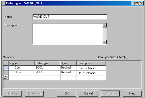
Now, make a UDT called VALVE, and ‘nest’ these sub-UDTs in it:
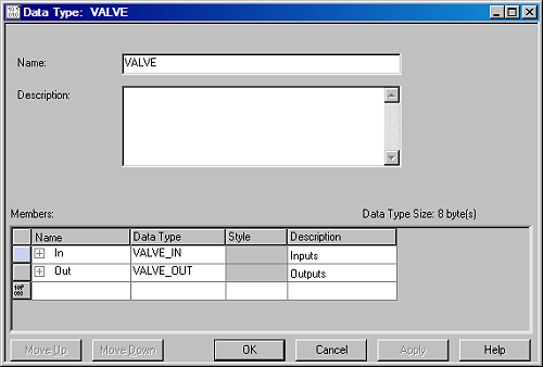
As you see, I am allowed to take the types I just created as the data type in this UDT. The real advantage of this feature will become clear if you create a object called Valve001 of the type VALVE, and look at the object in the ‘monitor tags’ window:
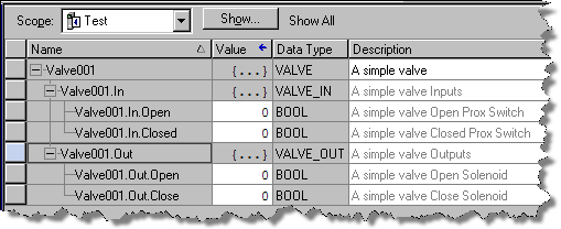
Wow! Just by creating a new tag of the type VALVE, it gets all these I/O points right away, and referenced in the program:
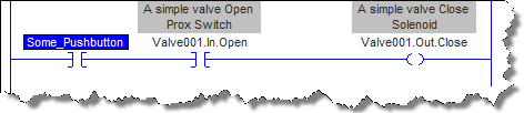
Of course, going further with this concept, everything for a valve can be included in one object. Allow me to skip some steps, and show you a possible final result:
The ‘VALVE’ class is now contained in a UDT called VALVE, which looks like this:

As you see, the class VALVE now consists of the sub-classes VALVE_IN, VALVE_OUT, VALVE_TIMER, VALVE_STATUS, etc.
And an instance of this class, the object Valve001, would look like this:
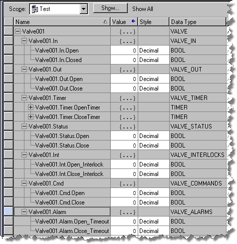
While adding stuff to my class, I did not have to re-create the object Valve001. RSLogix updated it for me, so all the properties and methods are available in my program.
Now, let’s say you’re working on this project with a couple hundred valves, and the customer decides to go with a different type of valve, that also has an analog input, that tells us the exact position of the valve. All we have to do is modify our VALVE_IN sub-class to add this to every instance of the type VALVE:

Of course, you would still have to write code to tell your program what to do with that information, but that is also the reason why PLC programmers still have a job.
For somebody that is not familiar with your program, it might be confusing to look at all your UDT’s. We just made eight UDT’s for one simple valve class! But remember, you only have to do this during the design phase. Once you have a solid design for all your classes (and made sure their names are self-explanatory), you will never have to look at your UDT folder again, and creating a new instance will be a breeze.
Connecting Excel to ControlLogix
by John Schop
Have you ever lost data in a CLX processor, because you downloaded new code? Unfortunately, when you donwload a program to a ControlLogix processor, you also download the values of the tags (variables).
A solution to this problem that could be useful, is an Excel sheet that reads and writes values to the ControlLogix processor using the DDE/OPC capabilities of RSLinx.
In this article, I will show you how to create one of these sheets for your projects.
Here's what you'll need:
- Microsoft Excel, with some basic knowledge about programming macro's in Visual Basic
- RSLinx (not the 'Lite' version, because that does not have DDE/OPC capabilities)
- A ControlLogix processor of course
Let's fire up RSLogix first, and create a bunch of tags with values. In this example, I created 2 arrays, of the types DINT and REAL, each with a length of [10] tags. These arrays I filled with some values:
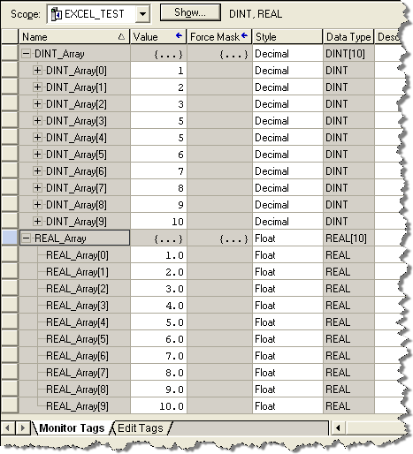
I'm not going to do anything with the PLC program, I just need some data in a number of tags.
Next, we're going to set up a DDE/OPC Topic in RSLinx. Depending on the version of RSLinx you use, it might look slightly different, but you should be able to follw this with the screenshots.
Assuming that you know how to setup RSLinx initally to get online with your controller, I've skipped some steps. The setup I use looks like this in RSLinx:
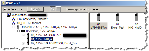
As you can see, I have a 10 slot CLX rack, with a 1756-ENBT card in slot 1 (address 134.200.211.16), and two processors, one in slot 0, and one in slot 2. The one in slot 2 is the processor we are going to use for this exercise.
Now, open up the DDE/OPC topic configuration by clicking 'DDE/OPC' and then 'Topic Configuration' in the top menu of RSLinx.
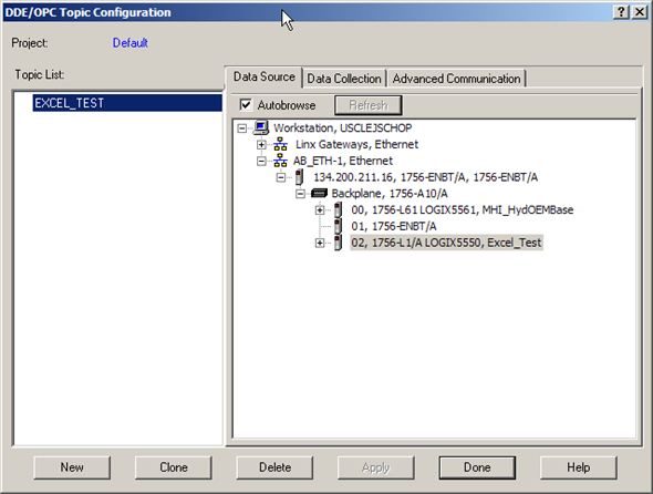
I'm going to create a new DDE/OPC topic called 'EXCEL_TEST', and use the Logix5550 processor in slot 2 as the data source. In order to do this, you have to click the 'New' button, give the topic the desired name, and make sure the processor in slot 2 is selected as the source before you click 'Done'
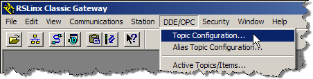
To test if your setup is working, at this point you can use the OPC test client provided with RSLinx. I'm not going into detail about that, but I did make sure this worked before continuing with the next step, creating the Excel sheet.
Let's start up good old Excel, and create a new workbook. On this workbook, place a new command button. You can find the Command Button control in the 'Control Toolbox' toolbar in Excel. When you have the button, right click on it and choose 'View Code'. This will take you to the Visual Basic Editor:
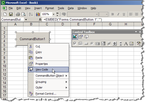
First, create a function that will open the DDE topic to Excel:
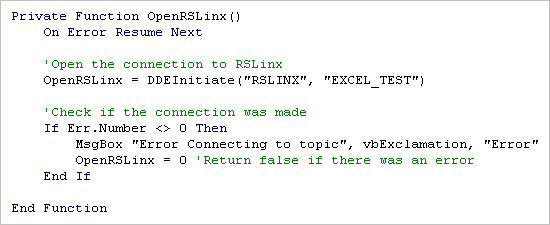
Now, if I call this function from the CommandButton1_Click event, it will open the link to RSLinx:
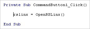
The variable 'rslinx' will hold the number of the open channel. All subsequent DDE functions use this number to specify the channel.
To save you all the steps to program the rest of the code, here is the final code to get the array of REALs out of the controller, and put them in cells D2 – D11, and the array of DINTs in cells E2-E11.
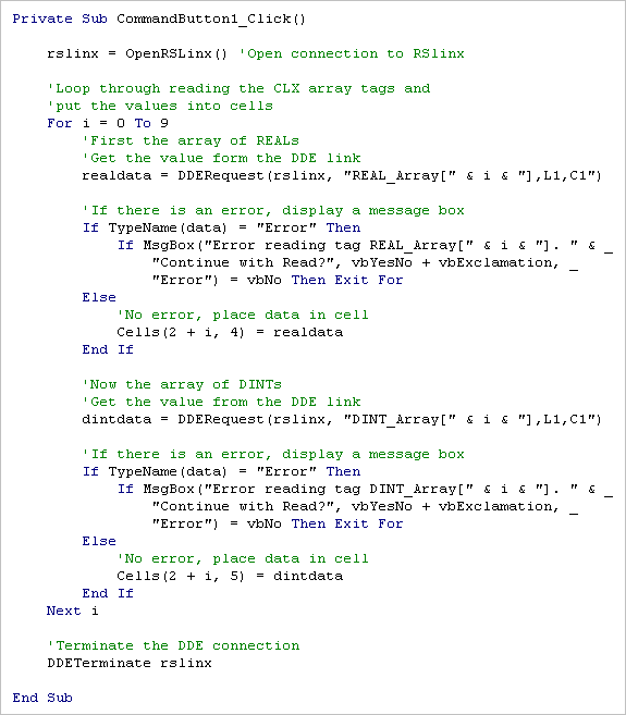
Now we know how to read, it would of course be a lot of fun if we could write values as well. I would like to be able to change the values in the cells, and then hit a 'Write Data' button.
First, make another button on the sheet (mine looks like below now)
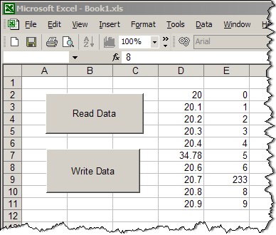
And then write some code for the button:
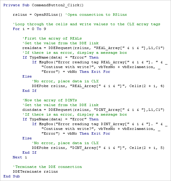
The way this is implemented is of course very rudimentary, but once you get the concept, the sky is the limit.
To make this easier on everybody, I've included the Excel file with the code already in it. The only thing you have to do to make this Excel sheet work, is make sure there is an DDE/OPC topic in your RSLinx setup called 'EXCEL_TEST', and the arrays REAL_Array and DINT_Array in your controller (of at least length 10).