Technical Information Page
Green
Spot Technical Information
The Green Spot is designed for simplicity and reliability of operation.
The Green Spot features a "pop-off" lid for access to the lamp
reflector assembly, a big feature for intensive manufacturing line operations
where down-time maintenance must be kept to a minimum. This feature allows
the user to change lamp reflector assemblies in less than a minute.
The Green Spot uses an industry standard super-pressure mercury
100-watt lamp, mounted vertically, in a dichroic-coated elliptical
reflector to generate an intense, consistent, 5mm spot of
light in the UVA, UVB, UVC and visible ranges. This light
is delivered through a standard-length, 1000mm liquid-filled
light guide to any small application requiring a UV adhesive,
coating or ink. The optics system contains a quartz IR filter
that allows UV light to pass from the 300-480nm range. This
filter may be removed for UV chemistries that require activation
in the 200-300nm range or other visible ranges above the UV
range for visible cure chemistries.
The Green Spot is powered by a solid-state, power-regulated
power board designed to maintain 100 watts of continuous power
to the lamp. The power board is auto-sensing between 110VAC,
60hz and 220VAC, 50hz, for use both domestically and overseas.
The power input module is fused for 4 amps with an extra fuse
provided. The power board is cooled by two low-cfm fans to
provide a consistent operating environment and can operate
in a temperature range from 52°F to 100°F.
The Green Spot is in an attractive, all anodized aluminum (both inside
and out) enclosure to provide for clean-room operations as well as "cool
to the touch" running of the machine. It has vent holes around the
back of the external casing to allow proper ventilation and to prevent
cooling blockage.
The Green Spot also features a gravity-close shutter system for safety
to the operator and reduced risk of the shutter being stuck in the open
position. The solenoid offers reliable performance for 100% duty cycles
up to the default timer maximum of 99 seconds. This has been tested in
excess of 10,000 repetitions. An air-operated shutter system is also available.
The exposure timer can be activated by a PLC or initiated by an operator
with a foot switch by way of an RCA jack located on the back of the unit.
There is a switch in the back to allow the operator to use either the
timer for exact, repeatable time exposures, or manual exposure using the
foot switch.
Lamp intensity of the Green Spot starts in excess of 5000 mw and, over
the life of the lamp, degrades to 40% of initial output after 1000 lamp
hours. This is a standard characteristic of all arc lamps. Since most
UV chemistries need less than 1000 mw of UV to initiate proper chemical
reaction with the photo initiator, the 2000 mw of power toward the end
of lamp life is more than twice that needed to provide proper UV chemical
reaction.
The Green Spot uses a liquid-filled light guide to deliver UV and visible
light to the point source from the optics system. The liquid
is a saline solution and is non-toxic if broken. The light
guide is coated inside with a space-age material for maximum
reflectance of light entering and exiting the quartz lenses.
The manufacturer holds international patents. The Green Spot
has a lamp-hour meter that can be reset after each lamp reflector
change. UV Source warranties lamps for 200 hours, unconditionally.
From 200 to 500 hours, we will prorate usage on the difference
between 200 and 500 hours. In foreign countries, line conditioning
may be necessary to ensure proper input voltage and current
control and thus we cannot offer this warranty until this
is verified.
We have leading-edge, high-technology access to both engineering
and manufacturing methods as they relate to the UV industry.
Quality, reliability and service are a must with our flagship
product, the Green Spot. We are committed to customer satisfaction
and references are provided upon request. We are here to help
you with your UV spot-curing applications.
UV Transmission Chart
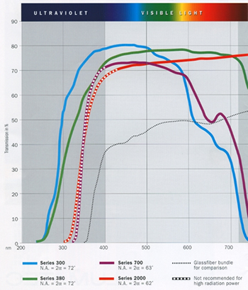
Light Guides
The standard light guide is designed to operate in the 320-500nm
range; however, we do sell a modified version that will operate
more efficiently in the UVB and UVC spectrum. (See Spectral
Chart above.)
The light guide degrades over time because of the UV exposure.
We recommend comparing used light guides to a new light guide
standard every 30-60 days. Significant reduction in UV transmittance
may occur and the UV intensity may be reduced by as much as
50% after 1 year of use depending on usage and exposure times.
The light guide is designed to bend slightly. This usually
means no more than a 90-degree bend over a 12" radius.
Reduction in UV output may occur.
The tips of the light guide are made of quartz and should be cleaned
with alcohol on a regular basis to eliminate dust, etc. If
UV glue is present on the tip, it will cure and become UV
blocking, significantly reducing UV output—as much as
100%.
If the IR filter on the Green Spot is damaged, broken or
clouded, the UV intensity output can be significantly less,
as much as 75%, and needs to be checked as part of regular
maintenance. Remove the light guide and look at the glass
filter with the machine off and turned upside down, and the
lid removed. If it appears bubbled, darkened or cracked, it
is a sign that it needs to be removed and replaced. Please
refer to the directions below.
IR Filter Replacement
Tools needed: Snap-ring pliers and a 3/32 bondus.
TURN OFF POWER TO UNIT AND UNPLUG FROM POWER SOURCE. Remove lid and
allow to cool for 5 minutes.
Please read all directions before attempting this. (See diagram
below)
1. Remove lamp reflector assembly completely and set aside. Be careful
not to touch any part of the glass lamp or glass reflector.
2. Remove 3 screws from around the light guide receptacle on the front
of the machine. This allows the optics system containing the
IR filter to be removed from the Green Spot. Be careful when
removing. The shutter will be free and will drop out. Note
the layout of the shutter position. This must be reassembled
exactly as is to ensure the shutter operates correctly when
reassembled. Make sure not to bend the shutter in any way.
Bending will render the shutter useless and a new one will
need to be ordered.
3. After removal of the optics system, you will be able to see the IR
filter at one end of the system. There are 2 more screws that hold the
square housing in place. Remove these 2 screws.
4. After removal of the square lamp reflector subassembly,
you will see the IR filter in the recessed end of the optics
system. Use snap-ring pliers to carefully remove the snap-ring
retainer. There are uv resistant coated washers holding the IR filter in
place. Make a note of their position if needed later for replacement
of the IR filter. Save these parts and store the filter in
a scratch-resistant container in case it is needed at a later
time. Be careful not to touch the IR filter with bare skin.
5. Reassemble the square lamp reflector subassembly with the optics system
and ensure the shutter is in correctly and sliding freely. The bottom
tab on the shutter that sticks out must be pointing towards the front
of the machine and resting on the top of the solenoid pin when inserted
back into the machine. The machine will not operate correctly if this
is not done.
6. Insert the optics system back into the machine and rescrew with the
3 original screws. There is a little play in the position of the optics
system when placing in the hole. Position the optics system as far to
the top of the machine as possible.
If you have any questions regarding this procedure, please call UV Source
at 1-800-783-1548.
|