BiRa Systems |
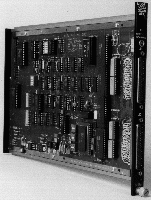
32-CHANNEL SCANNING ANALOG/DIGITAL CONVERTER 
The Bi Ra Model 5333B is a single-width module with 32 differential inputs via two front panel Type D connectors. Inputs are multiplexed through Harris HI-507A OVP muxes to a unity gain instrumentation amplifier followed by a Harris HI 5320 Sample/Hold and a 12-bit industry standard ADC 85 with five selectable full scale input voltage ranges; Bipolar 2.5, 5.0, 10.0 and Unipolar 5.0, 10.0.
Inputs are sequentially scanned beginning with Channel 0. The number of channels and the scan rate of the active channels are selectable. Time required for each channel is 10 microseconds. The number of channels scanned may be selected from 1 through 32 in unity increments. Repetition rate of a complete scan may be either external or internal. Single scan mode raises LAM at the end of a scan. Converted analog data continually updates a bipolar RAM at the scan rate. Data may be asynchronously read from memory without disrupting the scan by (FO & F1) or by F2 AO Block transfer, which interrupts the scan; data is read sequentially beginning with Channel 0. Data is presented to the dataway as a 16-bit 2’s complement word. For bipolar, the sign is extended to 16 bits. R1 through R16 is converted data of the R17 through R21 channel. X is returned for all commands. Q is conditional.
| COMMAND | ACTION |
|---|---|
| (F0+F1)An | Read last converted channel data from RAM. F0 A0 through F0 A15 read channels 0 through 15, F1 A0 through F1 A15 read channel 16 through 31. Data R1((LSB)-R16 is converted data of R17-R21 Channel. When DB12=1 (See PARA 2.2.2) data is extended to 16 Bits. That is R13, R14, R15, R16=1. R22=0 indicates the channels were scanned and read within the last 0.75 seconds. Q is returned for valid data as controlled by the active number of channels. |
| F2 A0 | Initiate and Read data in BLOCK transfer mode. Q for valid data. First command returns no Q and sets up Block mode. Following successive commands return Q and valid data beginning with Channel 0 and ending with the last active channel determined by the selected channel length. Following read returns module to previous state and LAM is reset in Single Scan Mode. Block Mode requires total read of active channels or termination by (Z+C) or F9 A0. In Single Scan Mode, LAM is reset at end of active channel read. Data information is for (F0+F1)An. |
| F3 A0 | R1-Single Scan Mode, R2-Continuous Scan Mode, R3-Block Read Mode R4-ADC Range Select OK, R5 through R8-ADC Range Code bits. |
| F8 A0 | Test LAM. LAM is active in Single Scan Mode only. LAM is set at completion of scan of active channels. Q is returned if LAM is set and enabled. |
| F9 A0 | Terminates scan, resets LAM, and enables Continuous Mode. |
| F10 A0 | Resets LAM in Single Scan and terminates scanning in all modes. |
| F11 A0 | Disables LAM. Q if in Single Scan Mode. |
| F24 A0 | Disables Single Scan Mode and LAM. Enables Continuous Mode. |
| F25 A0 | Initiates scanning of active channels beginning with channel 0. Required after F9 A0, F24 A0, or (Z+C) to begin Continuous Scan. May be used to initiate a Single Scan. Command clears LAM in Single Scan Mode. |
| F26 A0 | Enables Single Scan Mode. Disables Continuous Mode. |
| F27 A0 | Test Continous Scan Mode. Q if true. |
| (Z+C)S2 | Same as F9 A0. |
| +6 Volts | 500 mA |
|---|---|
| +24 Volts | 100 mA |
Mating Connectors 5333-1, 37-Pin (male) Type D or 5333-2, 50-Pin (female) Type D.
| Feedback | info@bira.com | Home Page |
Bi Ra Systems,
Incorporated
2404 Comanche Road NE
Albuquerque, New Mexico 87107
Ph : 505-881-8887
Fax:505-888-0651