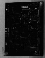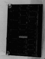

FASTBUS is a standardized modular data-bus system for data acquisition, data processing, and control. A FASTBUS system consists of multiple bus segments which can operate independently, but link together for passing data and other information. FASTBUS modules are housed in crates. One key feature of FASTBUS is that it allows multiple masters to reside and or access modules in a single crate. To accommodate this and other features of the specification as well as to provide terminators for ECL implemented bus, two logic boards are required and are housed at the rear of the crate, one board at each end. These are the Arbitration Timing Control (ATC) and the Geographical Address Control (GAC) modules. Together these modules are referred to as the Crate Segment Ancillary Logic. The Crate Segment Ancillary Logic, consisting of the Model 8177 (ATC) and the Model 8178 (GAC) modules, conforms to all mandatory and recommended features as specified in the December 1983 Department of Energy FASTBUS Specification (DOE/ER-0189, IEEE 960).

This circuitry detects requests for bus mastership from potential masters. When one or more requests are present and the previous master has released its control of the bus, this logic initiates an arbitration cycle, granting bus mastership to the highest priority requestor at the completion of the cycle. When potential bus masters are working in an "assumed access" mode, this logic also inhibits these masters from asserting new bus requests until all devices currently requesting the bus have been granted bus mastership.
Each FASTBUS crate has a bar across its lower front panel. All modules in a crate must be properly inserted before this bar can be put into its locked position. In this position, the bar forces a Run/Halt switch into its "Run" position. The Run/Halt Control Logic senses the position of this switch enabling bus activity (i.e. bus mastership requests) when the switch is in the "Run" position and disabling this activity when the switch is in the "Halt" position (i.e., bar in its unlocked position).
During FASTBUS Broadcast operations addressed modules do not return any address or data acknowledge handshake signals to the Broadcast master. Since Broadcast messages can be sent to several devices in several crates simultaneously, the Broadcast master must be provided with handshake signals which insure that even the most remotely distant addressed module has time to respond. The system Handshake Logic provides these signals.
An 82 ohm resistor to 2.0V is included for each bus line requiring an ECL termination.

There are three addressing modes in FASTBUS. One mode, called Geographical Addressing used for system/device initialization and typically for addressing simple and front-end modules, is dependent upon the physical position of a module in a crate. To reduce circuitry in geographically addressed monitors, The Geographical Address Control Logic monitors the bus for geographic addresses. If one such address is detected, this logic asserts a signal indicating to slaves that the current address on the bus is geographical. A slave detecting this signal must then only decode a few bits rather than the full 32 bits to determine if it is being geographically addressed.
This logic provides logic 1 and logic 0 levels at specified pins such that, via backplane bussing, the signals on the five Geographical Address pins at each slot in a crate are the binary number of the physical position of the slot in the crate. For example, slot 25 would have the logic states 11001 on these five pins, slot 14 01110, etc.
Addressing CSR 1 on the GAC module will return on the upper data lines the states of a twelve-position switch. This switch enables the system software to uniquely identify a bus segment for diagnostic purposes.
Same as the ATC module.