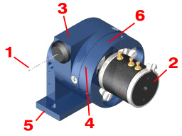
Analog-Output Miniature Position Transducers
Shaded characteristics are verified during production and test. All others are for REFERENCE and information only.
Key Features
- 42.5-Inch (1080-mm) Maximum Travel (Series 162)
- Analog Signal Using Precision Conductive Plastic/Hybrid Potentiometers
- AccuTrak™ Threaded Drum for Enhanced Repeatability
- Bearing-Mounted Rotating Components
- Optional Flexible Mounting Bases
- DirectConnect™ Sensor-To-Drum Technology = Zero Backlash, No Torsion Springs or Clutches
|
 |
Potentiometer Specifications
| |
1-turn |
3-turn |
5-turn |
| Potentiometer Type |
1-turn, precision, conductive plastic |
3-turn, precision, hybrid |
5-turn, precision, hybrid |
| Resistance: Value, Tolerance |
5K ohms, ±20% |
5K ohms, ±5% |
5K ohms, ±5% |
| Travel: Electrical, Mechanical |
340°, 360° |
1080°, 1080° +10° -0° |
1800°, 1800° +10° -0° |
| Mechanical Life |
10 million shaft revolutions min |
5 million shaft revolutions min |
5 million shaft revolutions min |
| Output Signal |
analog signal from 0 to supply voltage
(voltage divider circuit) |
| Power Rating |
1.0 W at 158° F (70° C) |
1.5 W at 158° F (70° C) |
2.0 W at 158° F (70° C) |
| Supply Current |
12 mA max |
| Supply Voltage |
35 VDC max (using voltage divider
circuit) |
| Independent Linearity Error |
±1.0% max per VRCI-P-100A |
±0.5% max per VRCI-P-100A |
±0.35% max per VRCI-P-100A |
| Output Smoothness |
0.1% max |
0.5% max |
0.35% max |
| Insulation Resistance |
100 Mohms at 1000 VDC min |
1000 Mohms at 500 VDC min |
1000 Mohms at 500 VDC min |
| Dielectric Strength |
1000 VDC min |
1000 VDC min |
1000 VDC min |
| Resolution |
infinite signal |
infinite signal |
infinite signal |
| Operating Temperature |
-40° to 257° F (-40° to 125° C) |
-67° to 257° F (-55° to 125° C) |
-67° to 257° F (-55° to 125° C) |
| Electrical Connection |
3-terminal (1, 2, 3) |
3-terminal (CW,CCW,S) |
3-terminal (CW,CCW,S) |
| Shock |
50 g for 11 ms |
100 g for 6 ms |
100 g for 6 ms |
| Vibration |
10 to 2000 Hz at 15 g |
10 to 2000 Hz at 15 g |
10 to 2000 Hz at 15 g |
| Temperature Coefficient |
±400 ppm/°C max |
±0.007%/°C max |
±0.007%/°C max |
The potentiometer type of a specific position transducer part number
is designated by the 8th digit of the part number counting left to
right. Example: 160-0321-C5SS contains a 1-turn potentiometer while
161-2405-D7NU contains a 5-turn potentiometer.
Other Specifications
| Case/Drum Materials |
precision-machined anodized 2024 aluminum |
| Displacement Cable |
0.018-inch (0.46-mm) dia., 7-by-7 stranded stainless steel, 40-lb (177-N) min breaking strength |
Displacement
Cable Hardware |
1 each of 300196 loop sleeve, 300292 copper sleeve, 300688 ball-end plug, 300495 pull ring, 160026 brass swivel, and 301003 nickel swivel; all items provided uncrimped |
| Electrical Connections |
three solder terminals; electrical cable and connector options available |
| Nominal Mass |
| Series 160 |
Series 161 |
Series 162 |
| 4 oz |
113 g |
6.1 oz |
170 g |
9 oz |
255 g |
|
| Environmental Protection |
NEMA 4 / IP 56, DO-160D (ED-14D) Env. Cat. E1E1ABXHRFDFSAXXXXXXXXXX (with optional
sensor cover) |
Model Numbers and Ordering Codes
| Model |
Range |
Nominal Displacement Cable Tension Range (Full Retraction to Full Extraction) |
| inches |
mm |
Opt 5: -050 spring |
Opt 6: -060 spring |
Opt 7: -070 spring |
Opt 8: -080 spring |
| oz. |
N |
oz. |
N |
oz. |
N |
oz. |
N |
| 160-0161 |
2.00 |
51 |
9 to 15 |
3 to 4 |
16 to 25 |
4 to 7 |
30 to 37 |
8 to 10 |
40 to 55 |
11 to 15 |
| 160-0241 |
3.00 |
76 |
7 to 12 |
2 to 3 |
10 to 18 |
3 to 5 |
17 to 30 |
5 to 8 |
40 to 55 |
11 to 15 |
| 160-0321 |
4.00 |
102 |
4 to 8 |
1 to 2 |
5 to 12 |
1 to 4 |
12 to 20 |
3 to 6 |
28 to 55 |
7 to 16 |
| 160-0483 |
6.00 |
152 |
10 to 21 |
3 to 6 |
12 to 30 |
3 to 8 |
48 to 72 |
13 to 20 |
75 to 160 |
21 to 45 |
| 160-0643 |
8.00 |
203 |
7 to 17 |
2 to 5 |
9 to 24 |
3 to 7 |
22 to 38 |
6 to 11 |
40 to 120 |
11 to 33 |
| 160-0803 |
10.00 |
254 |
6 to 13 |
2 to 4 |
8 to 19 |
2 to 5 |
16 to 32 |
4 to 9 |
35 to 100 |
10 to 28 |
| 160-0963 |
12.00 |
305 |
5 to 11 |
1 to 3 |
7 to 19 |
2 to 5 |
14 to 27 |
4 to 8 |
24 to 82 |
7 to 23 |
| 160-1085 |
13.50 |
343 |
7 to 20 |
2 to 6 |
12 to 28 |
3 to 8 |
18 to 53 |
5 to 15 |
30 to 134 |
8 to 37 |
| 160-1285 |
16.00 |
406 |
6 to 17 |
2 to 5 |
8 to 24 |
2 to 7 |
19 to 40 |
5 to 11 |
17 to 102 |
5 to 28 |
| 160-1505 |
18.75 |
476 |
5 to 14 |
1 to 4 |
8 to 22 |
2 to 6 |
15 to 39 |
4 to 11 |
24 to 90 |
6 to 26 |
| 160-1705 |
21.25 |
540 |
5 to 12 |
1 to 3 |
7 to 19 |
2 to 5 |
12 to 33 |
3 to 9 |
14 to 79 |
4 to 22 |
| 161-0461 |
5.75 |
146 |
- |
- |
4 to 15 |
1 to 4 |
13 to 32 |
4 to 9 |
35 to 50 |
10 to 14 |
| 161-1283 |
16.00 |
406 |
- |
- |
6 to 12 |
2 to 3 |
10 to 25 |
3 to 7 |
14 to 70 |
4 to 19 |
| 161-1915 |
23.88 |
606 |
- |
- |
5 to 17 |
1 to 5 |
13 to 30 |
4 to 8 |
16 to 80 |
4 to 22 |
| 161-2145 |
26.75 |
679 |
- |
- |
7 to 14 |
2 to 4 |
10 to 25 |
3 to 7 |
11 to 60 |
3 to 17 |
| 161-2405 |
30.00 |
762 |
- |
- |
5 to 12 |
1 to 3 |
8 to 23 |
2 to 6 |
9 to 60 |
3 to 17 |
| 162-2735 |
34.13 |
867 |
- |
- |
- |
- |
8 to 21 |
2 to 6 |
10 to 55 |
3 to 15 |
| 162-2945 |
36.75 |
933 |
- |
- |
- |
- |
7 to 20 |
2 to 6 |
15 to 44 |
4 to 12 |
| 162-3205 |
40.00 |
1016 |
- |
- |
- |
- |
7 to 18 |
3 to 5 |
10 to 43 |
3 to 12 |
| 162-3405 |
42.50 |
1080 |
- |
- |
- |
- |
7 to 17 |
2 to 5 |
8 to 41 |
2 to 11 |
Bolded entries are standard cable tension.
Order Codes
| 16_-_ _ _ _-abcd (example: 160-0321-S5SB (cable exit: slot, cable tension: -050, sensor cover, and base: big foot) |
| Series 160 |
a |
S |
cable exit: slot (_60) |
| C |
cable exit: cable guide |
| D |
cable exit: idler (_60); pn 160022 |
| R |
cable exit: RoundAbout™; pn 301224 |
| b |
5 |
cable tension: -050 |
| 6 |
cable tension: -060 |
| 7 |
cable tension: -070 |
| 8 |
cable tension: -080 |
| c |
N |
no sensor cover (_60) |
| S |
sensor cover (_60); pn 160060 |
| d |
D |
base: mounting disk (_6_); pn 160040-1 (cannot be ordered with a = R (cannot be used with RoundAboutTM cable exit)) |
| S |
base: standard (_60); pn 160015-1 |
| U |
base: universal (_60); pn 160030-1 |
| B |
base: big foot (_60/_61); pn 160015-1_ |
| H |
base: h (_60); pn 160015-G1 |
| P |
base: universal (miniature) (_60); pn 300460 |
| Series 161 |
a |
S |
cable exit: slot (_61) |
| C |
cable exit: cable guide |
| D |
cable exit: idler (_61/_62); pn 161022 |
| R |
cable exit: RoundAbout™; pn 301224 |
| b |
5 |
cable tension: -050 |
| 6 |
cable tension: -060 |
| 7 |
cable tension: -070 |
| 8 |
cable tension: -080 |
| c |
N |
no sensor cover (_61) |
| S |
sensor cover (_61); pn 160060 |
| d |
D |
base: mounting disk (_6_); pn 160040-1 (cannot be ordered with a = R (cannot be used with RoundAboutTM cable exit)) |
| S |
base: standard (_61); pn 160015-3 |
| U |
base: universal (_61); pn 160030-3 |
| B |
base: big foot (_60/_61); pn 160015-1_ |
| Series 162 |
a |
S |
cable exit: slot (_62) |
| C |
cable exit: cable guide |
| D |
cable exit: idler (_61/_62); pn 161022 |
| R |
cable exit: RoundAbout™; pn 301224 |
| b |
5 |
cable tension: -050 |
| 6 |
cable tension: -060 |
| 7 |
cable tension: -070 |
| 8 |
cable tension: -080 |
| c |
N |
no sensor cover (_62) |
| S |
sensor cover (_62); pn 160060 |
| d |
D |
base: mounting disk (_6_); pn 160040-1 (cannot be ordered with a = R (cannot be used with RoundAboutTM cable exit)) |
| S |
base: standard (_62); pn 160015-_ |
| U |
base: universal (_62); pn 160030-_ |
| B |
base: big foot (_62); pn 160015-1_ |
Displacement Cable Maximum Acceleration by Model Number
| Model |
Max Cable Acceleration (g's) |
| Opt 5: -050 spring |
Opt 6: -060 spring |
Opt 7: -070 spring |
Opt 8: -080 spring |
| 160-0161 |
10 |
19 |
35 |
46 |
| 160-0241 |
14 |
22 |
123 |
82 |
| 160-0321 |
8 |
10 |
23 |
69 |
| 160-0483 |
38 |
54 |
173 |
357 |
| 160-0643 |
43 |
55 |
147 |
427 |
| 160-0803 |
38 |
64 |
121 |
242 |
| 160-0963 |
30 |
42 |
103 |
182 |
| 160-1085 |
55 |
65 |
109 |
165 |
| 160-1285 |
42 |
47 |
99 |
105 |
| 160-1505 |
16 |
49 |
98 |
127 |
| 160-1705 |
30 |
40 |
75 |
70 |
| 161-0461 |
5 |
8 |
16 |
23 |
| 161-1283 |
- |
38 |
76 |
126 |
| 161-1915 |
- |
72 |
133 |
205 |
| 161-2145 |
- |
70 |
130 |
201 |
| 161-2405 |
- |
56 |
72 |
95 |
| 162-2735 |
- |
- |
60 |
84 |
| 162-2945 |
- |
- |
48 |
73 |
| 162-3205 |
- |
- |
37 |
63 |
| 162-3405 |
- |
- |
31 |
45 |
Drawing: shown with slot cable exit, standard base, and optional sensor cover.
Drawing: shown with cable guide cable exit, standard base, and optional sensor cover.
Drawing: shown with idler cable exit, standard base, and optional sensor cover.
Idler cable exit will reduce displacement cable life
and may reduce maximum range by up to 0.75 inch (19.1 mm). Idler not
recommended for use with -080 spring.
Drawing: RoundAbout™ cable guide dimensional details
Electrical Schematic
For crimping of hardware to displacement cable, consider the 160001-01 installation kit.
Need something not shown? Complete a Custom Solution Request.
All dimensions are REFERENCE and are in inches [mm] • Data Sheet Series 160, 161 and 162 Rev. -
|