|
VME PROCESSOR MODULES | ||
 A photograph of a board in
 |
Part Number |
Description |
|
MVME2301 |
200 MHz MPC603, 16MB ECC DRAM, 5MB Flash |
|
MVME2302 |
200 MHz MPC603, 32MB ECC DRAM, 5MB Flash |
|
MVME2303 |
200 MHz MPC603, 64MB ECC DRAM, 5MB Flash |
|
MVME2304 |
200 MHz MPC603, 128MB ECC DRAM, 5MB Flash |
|
MVME2305 |
300 MHz MPC604, 16MB ECC DRAM, 5MB Flash |
|
MVME2306 |
300 MHz MPC604, 32MB ECC DRAM, 5MB Flash |
|
MVME2307 |
300 MHz MPC604, 64MB ECC DRAM, 5MB Flash |
|
MVME2308 |
300 MHz MPC604, 128MB ECC DRAM, 5MB Flash |
|
Note: MVME230x-900 series available with original style VMEbus ejector handles |
|
Related Products
|
PMCSPAN-002 |
Primary PCI expansion, mates directly to the MVME2300 providing slots for either two single-wide or one double-wide IEEE P1386.1 compliant PMC cards; optional PMCSPAN-010 |
|
PMCSPAN(1)-002 |
PMCSPAN-002 with original style VMEbus ejector handles |
|
PMCSPAN-010 |
Secondary PCI expansion, plugs directly into PMCSPAN-002 providing two additional PMC slots |
|
PMCSPAN(1)-010 |
PMCSAN-010 with original style VMEbus ejector handles |
|
MPMCxxx |
Motorola's family of PMC modules; ask your sales representative for details |
Documentation
|
V2300A/IH |
MVME2300 Installation and Use |
|
V2300A/PG |
Programmer's Reference Guide |
|
PMCSPANA/IH |
PMCSPAN Installation Guide |
|
PPCBUGA1/UM |
PPC1BUG User's Manual, Part 1 of 2 |
|
PPCBUGA2/UM |
PPC1BUG User's Manual, Part 2 of 2 |
|
PPCDIAA/UM |
Firmware Diagnostics Manual |
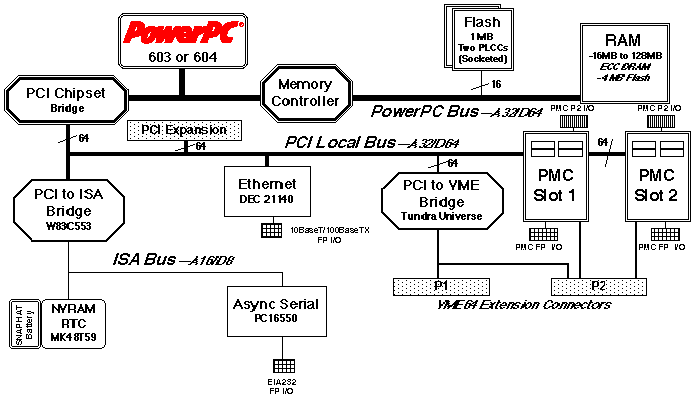
MVME2300 Block Diagram
IEEE P1386.1 Compliant PMC Slots
The MVME2300 features dual PMC ports with support for both front panel and P2 I/O. P2 I/O-based PMCs which follow the PMC committee recommendation for PCI I/O when using the VME64 extension connector will be pin-out compatible with the MVME2300.
In addition to providing high performance expansion I/O, the IEEE P1386.1 compliant PMC ports form a common architecture for future generations of products. Changing I/O requirements can be satisfied by simply replacing PMCs while reusing the same base platform, reducing the long-term cost of ownership.
VME64 Extension Connector
To maximize the capabilities of the MVME2300, 5-row 160-pin DIN connectors replace the 3-row 96-pin connectors historically used on VME for P1 and P2. Two rows, Z and D, have been added to the VME P1/J1 and P2/J2 connectors providing a user with additional I/O. The VME64 extension connector is 100% backward compatible with existing VME card systems.
PowerPlus Architecture
The PowerPlus Architecture is a processor and bus architecture fully optimized to get the maximum performance from the PowerPC
Ò microprocessor family, the PCI bus, and the VMEbus. The outstanding performance of VME processor boards based on the PowerPlus Architecture is not due to a single factor. A number of elements in the design of the PowerPlus Architecture contribute to its outstanding performance including the Processor/Memory subsystem, high-speed local bus, optimally decoupled architecture, decoupling the processor from PCI, and the advanced VME interface which reduces PCI delays. More detail is available on the PowerPlus Architecture in the MVME2600 datasheet. Contact your sales representative for details.Specifications
MVME2300 VME Processor Module
Processor
|
Microprocessor: |
MPC603 |
MPC604 |
|
Clock Frequency: |
200 MHz |
300 MHz |
|
On-chip Cache (I/D): |
16KB/16KB |
32KB/32KB |
|
SPECint95, measured: |
not available |
10.8 |
|
SPECfp95, measured: |
not available |
9.72 |
Memory
|
ECC Protected Main Memory: |
Dynamic RAM with 66 MHz bus |
|
Capacity (60ns EDO): |
16 or 32MB |
|
Capacity (50ns EDO): |
64 or 128MB |
|
Single Cycle Accesses: |
9 Read/4 Write |
|
Read Burst Mode (60ns): |
9-1-2-1 idle; 3-1-2-1 aligned page hit |
|
Read Burst Mode (50ns): |
8-1-1-1 idle; 2-1-1-1 aligned page hit |
|
Write Burst Mode: |
4-1-1-1 idle; 3-1-1-1 aligned page hit |
|
Architecture: |
128-bit, 2 way interleaved |
|
EEPROM/Flash: |
On-board programmable |
|
Capacity: |
1MB via two 32-pin PLCC/CLCC sockets; 4MB surface mount |
|
Read Access (4MB port): |
68 Clocks (32 byte burst) |
|
Read Access (1MB port): |
260 Clocks (32 byte burst) |
|
NVRAM: |
8KB; 4KB available for users |
|
Cell Storage Life: |
50 years at 55° C |
|
Cell Capacity Life: |
10 years at 100% duty cycle |
|
Removable Battery: |
Yes |
VMEbus ANSI/VITA 1-1994 VME64 (IEEE STD 1014)
|
DTB Master: |
A16-A32; D08-D64, BLT |
|
DTB Slave: |
A24-A32; D08-D64, BLT, UAT |
|
Arbiter: |
RR/PRI |
|
Interrupt Handler/Generator: |
IRQ 1-7/Any one of seven IRQs |
|
System Controller: |
Yes, jumperable or auto detect |
|
Location Monitor: |
Two, LMA32 |
Ethernet Interface
|
Controller: |
DEC 21140 |
|
PCI Local bus DMA: |
Yes |
|
Connector: |
Routed to front panel via an RJ-45 |
Asynchronous Serial Port
|
Controller: |
PC16550 |
|
Connector: |
Routed to the front panel via an RJ-45 |
Counters/Timers
|
TOD Clock Device: |
M48T59; 8KB NVRAM |
|
Real-Time Timers/Counters: |
Four 16-bit programmable |
|
Watchdog Timer: |
Time-out generates reset |
Miscellaneous
|
Front panel: |
Reset and Abort switches; four LEDs for Fail, CPU, PMC1, PMC2 |
IEEE P1386.1 PCI Mezzanine Card Slot
|
Address/Data: |
A32/D32/D64, PMC PN1, PN2, PN3, PN4 connectors |
|
PCI Bus Clock: |
33 MHz |
|
Signaling: |
5V |
|
Power: |
+3.3V, +5V, ±12V, 7.5 watts maximum per PMC slot |
|
Module Types: |
One double-wide or two single-wide front panel I/O or P2 I/O |
Note: P2 I/O from PMC slot 2 is only accessible to systems equipped for VME64 extension connectors
PCI Expansion Connector
|
Address/Data: |
A32/D32/D64 |
|
PCI Bus Clock: |
33 MHz |
|
Signaling: |
5V |
|
Connector: |
114-pin connector located on the planar of the MVME2300 |
Power Requirements
|
|
+ 5V ± 5% |
|
MVME2300 w/ MPC603 @ 200 MHz: |
4.0 A typical, 4.75 A max. |
|
MVME2300 w/ MPC604 @ 300 MHz: |
4.5 A typical, 5.5 A max. |
Note: Power requirements are PMC dependent at +12 and -12 volts.
Demonstrated MTBF
|
Mean/90% Confidence: |
190,509 hours/ 107,681 hours |
Board Size
|
Height: |
233.4 mm (9.2 in.) |
|
Depth: |
160.0 mm (6.3 in.) |
|
Front Panel Height: |
261.8 mm (10.3 in.) |
|
Width: |
19.8 mm (0.8 in.) |
|
Max. Component Height: |
14.8 mm (0.58 in.) |
Environmental
|
|
Operating |
Nonoperating |
|
Temperature: |
0° C to +55° C, forced air cooling |
-40° C to +85° C |
|
Altitude: |
5,000 m |
15,000 m |
|
Humidity (NC): |
10% to 80% |
10% to 90% |
|
Vibration: |
2 Gs RMS, |
8 Gs RMS, |
Regulatory Compliance
Intended for use in systems meeting the following EMI/RFI regulations:
|
US: |
FCC Class B |
|
Canada: |
DOC Class B |
|
Europe: |
VDE Class B, CISPR-B, CE Mark |
|
Safety: |
All printed wiring boards (PWBs) are manufactured with a flammability rating of 94V-0 by UL recognized manufacturers. |
Software Support
The MVME2300 is supported by a variety of operating systems, including a complete range of real-time operating systems and kernels.
For more information, visit our World Wide Web site at http://www.mot.com/computer/
For fax-back service dial 1-800-682-6128 in the U.S. and 602-438-4636 outside of the U.S.
To call us dial 1-800-759-1107 in the U.S. and 512-434-1526 outside of the U.S.
Corporate headquarters address: Motorola Computer Group, 2900 S. Diablo Way, Tempe, AZ 85282
Copyright 1997 Motorola, Inc.
Data Sheet: M2300-D3