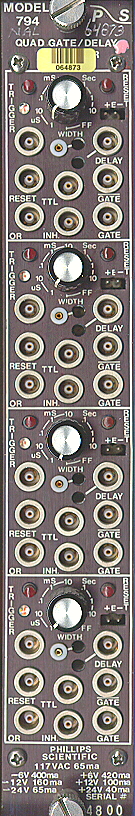
 MODEL 794 QUAD GATE/DELAY UNIT
FEATURES:
Wide Range - Less than 100 nSec to over 10 Sec
'Set - Reset' Flip-Flop Mode
No Deadtime
Computer/Remote Programming via a 0 Volt to 10 Volt Input
The Quad Gate/Delay Generator, Model 794, complies fully with the NIM specification TID-20893 and is packaged in a single width module. In 'monostable model, gate/delay periods may be adjusted either locally or remotely from less than 100 nsec to more than 10 seconds. Each channel also operates in a 'set-reset flip-flop' mode. A bright LED indicates an active, logic '1', gate condition. Versatile input and output structures provide compati- bility with NIM, ECL, and TTL standards. Further flexibility is afforded by programming jumpers mounted on the printed circuit board. These jumpers allow selected inputs and outputs to be assigned alternate logic functions or polarities.
TIME-BASE DESCRIPTION
The model 794 time-base circuit is non-updating and exhibits essentially no deadtime. Monostable gate/delay periods are selected by a combination of the "RANGE" switch and a time vernier potentiometer or, by jumper option, the "RANGE" switch and an analog pro- gramming input. A monitor test point provides a 0 to 1 Volt output which is proportional to the gate/delay period. Setting the gate/delay period with an oscilloscope is easily accomplished by using the "TRIGGER" pushbutton. Depressing this switch for more than 0.5 seconds causes the time-base to retrigger at a 1 KHz rate. In the bistable mode, the gate/delay period is equal to the interval between the arrival of the trigger and reset functions. The "DELAY" output always occurs at the trailing edge of the "GATE" output. The "DELAY" output width may be adjusted by a front panel potentiometer.
INPUT DESCRIPTION
There are three ways to trigger the Model 794: (1) "TRIGGER" input; (2) "OR" input; and (3) "TRIGGER" pushbutton. These functions are enabled in both monostable and bi-stable modes.
The "TRIGGER" input is compatible with both TTL levels and negative NIM logic. This input presents a high impedance to positive sigals and 50 ohms to negative signals. The time-base triggers on the leading edge of the input pulse regardless of its polarity. The gate period is independent of the "TRIGGER" pulse width.
"OR" is a negative NIM logic input which is configured with program jumpers. The "OR" input is always logically 'OR'ed with the time-base output. Assuming a quiescent time-base, the "GATE" output width is equal to the "OR" input width. A program jumper enables the 'input OR' mode in which the "OR" input also triggers the time-base. 'Input OR' mode produces a "GATE" output equal to the width of the "OR" input or the preset time whichever is greater. An additional jumper allows "OR" to be a high impedance or 50 ohms. Note that the high impedance 'input OR' mode allows multiple channels or multiple modules to be triggered from a single output, i.e., high impedance pick-off.
The "TRIGGER" pushbutton offers two operating modes for manual triggering. 'Single trigger' mode is executed by pushing and releasing the switch in less than 0.5 seconds. This produces a single trigger pulse. 'Retrigger model is executed by pushing and holding the switch for more than 0.5 seconds.
Page 2