|
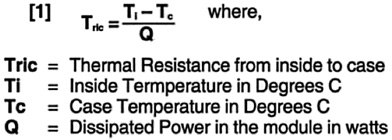
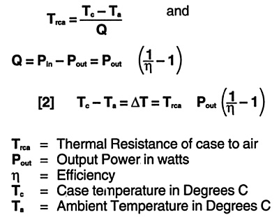
To use these PICO Series at full power one has to get rid of dissipated losses in the modules. Although the high efficiency of these units minimizes the heat loss; The exposed area, depending on the ambient temperature, may not be enough to keep the case temperature at an acceptable value if natural convection is used. The additional heat may be removed by a heat sink, forced air, or both. Internal losses produce heat which is moved toward the case and must be removed. Depending on the thickness and the material used, there is always a temperature gradient from inside to the case which may be calculated by:
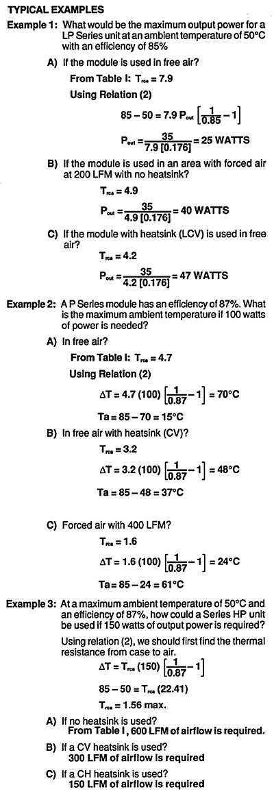
The specification given in the data sheet of these units are such that at 85° C case the Ti; (inside temperature of components) is acceptable for proper operation. The user of these modules then has the task to keep the case temperature at or below 85° C. The temperature rise of the case depends on how efficiently the heat is removed. If the process is very efficient the thermal resistance is low and the case to ambient temperature gradient is low. The thermal resistance from the case to the air is given by:
The following table shows the Thermal Resistance in free air as well as with forced cooling with or without heat sinks.
Table 1:Thermal resistance case to air (° C/W) | |||||||||
| . | Series LP/LF/LM | Series P | HP/XP/M Series, also Series P High Voltage Only | ||||||
|---|---|---|---|---|---|---|---|---|---|
| Baseplate | Heatsink LCV |
Heatsink LCH |
Baseplate | Heatsink CV |
Heatsink CH |
Baseplate | Heatsink CV |
Heatsink
| |
|
|
|
|
|
|
|
|
|
|
|
|
|
|
|
|
|
|
|
|
|
|
|
|
|
|
|
|
|
|
|
|
|
|
|
|
|
|
|
|
|
|
|
|
|
|
|
|
|
|
|
|
|
|
|
|
|
|
|
|
|
|
|
|
|
|
Output Voltage Trimming:
The output voltage of Pico's LP, P, and HP units can be adjusted to within ± 5% of the nominal setting by placing a resistor between the "TRIM UP" and the "TRIM DOWN" pins respectively.
Due to internal tolerances, the values presented in the table are
typcial. To quickly select the right resistance to achieve the desired
adjustment, a multi-turn trimmer potentiometer (1M ohms) is recommended.
Keep the trim resistor leads as short as possible to eliminate the stray
inductance which will effect the trimming results.
 |
 |
* For LP/LF/LM Models: Trim up by adding the resistor between the Trim
Pin and the -Input. Use these same resistors values.
| *Typical Resistance Range for Trim UP and Trim Down | ||||
|
|
|
|
|
|
|
Resistance |
|
|
|
|
|
Resistance |
|
|
|
|
For parallel operation, the corresponding pins of the units must be connected together. The paths of these connectiosn should be as direct as possible. The path to the load also should have the lowest possible resistance; otherwise unacceptable losses and load regulation will occur. For instance, a 1 milli-ohm resistance and a 100 ampere load will cause 10 watts of line losses as well as additional load regulation.
If the parallel configuration is for redundant operations, schottky diodes should be used at the output of each module as shown.
For parallel operation, add suffix P to Part #. Example: PA5SP, PB5SP, PC5SP, PD5SP.