When the magnets were warmed up to room temperature, it seemed like a
good opportunity to verify
the wiring of the quench protection circuits and get some resistance
measurements that might be compared to any
historical values that could be found. Shortly into this operation it
was found that the panel meters used on
the Q1 magnets, on both arms, were at best erratic and at worst
non-functional. Unfortunately, it was not anticipated that
there would be further complications with the magnets and that exact
location and problem information of the
meters might be of value. Other than the notes I made in the logbooks,
there is no possibility of retrieving further
information about the performance of specific meters.
It was decided to use the Danfysik quench detection circuits
Hall A already had on hand to implement
replacement quench detection circuits, as a temporary measure until
permanent replacements could be
fabricated or procured. While installing and verifying the operation of
these circuits, it was found that the voltage
drops across the warm to cold transition leads were higher than
expected and in one case significantly so.
Upon further invstigation it was found the beam right lead of the RQ1
magnet had a non-linear voltage
drop with respect to the current carried by the lead.

Below, we can see the performance of the LQ1 leads with respect
to the
lead flows. The currents in the magnet were
800 amps and 1600 amps. Notable decreases in the voltage drops were
made at 1600 amps as the lead flows were
increased.

This leads to the thought that the generally high voltage drops
observed might be due in part to lower
flow rates than were originally used during the comissioning of the
magnets. This would not cover the behavior of the RQ1
beam right lead, however.
The voltage drop across the RQ1 beam right lead did not increase
and decrease as expected. There was found to be a region
of flow that would cause an increase in the voltage drop as the flow
rate was increased, counter to expectations.

There were some indications of instability in the voltage drop across
the RQ1 beam right lead. The voltage increase non-linearly and then had
a long droop. A small subsequent increase in the current also had a
large increase in the voltage drop with an extended recovery period.

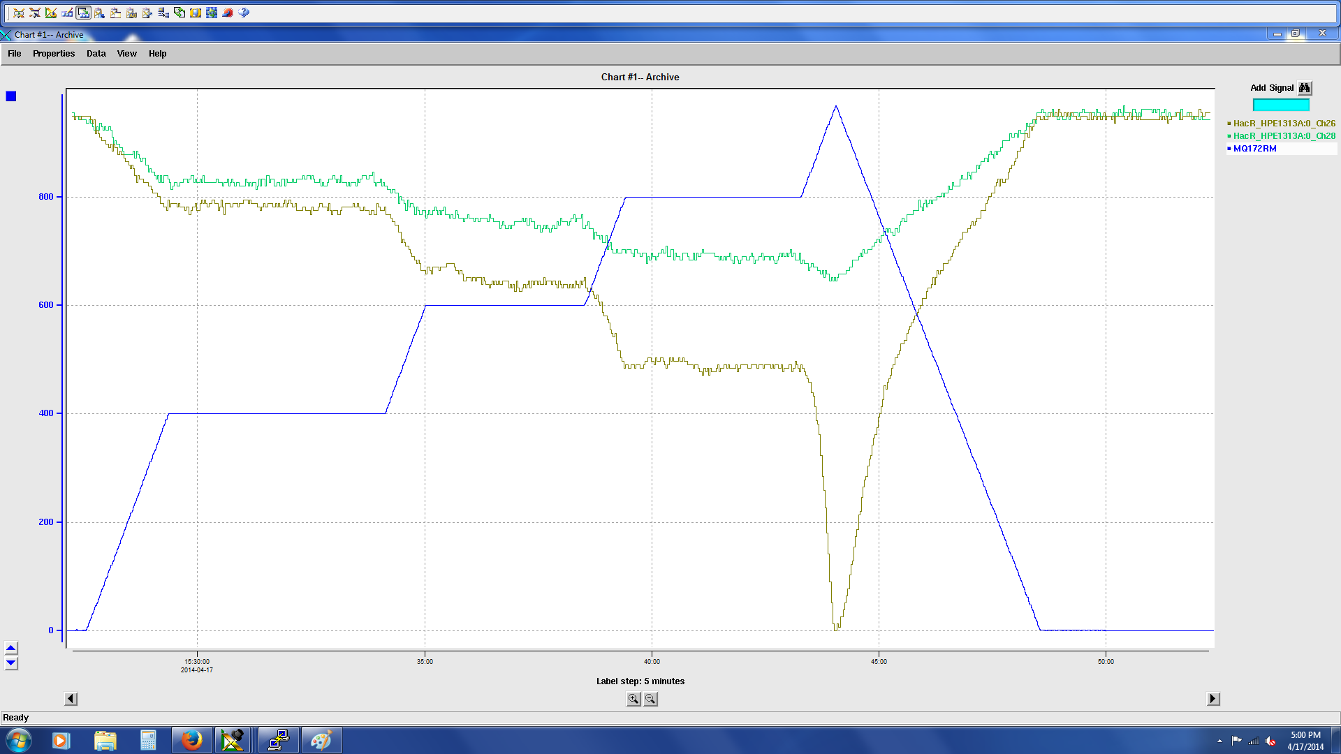
In light of the behavior noted above, and given that we had some prior
evidence that the lead voltage protection circuit did cause the power
supply to disconnect on an excessive volatge drop across the leads, it
was decided to drive the current slightly higher. The voltage drop
across the lead can be seen to be taking off as we were ramping from
800 amps to 1000 amps. The set current was reduced to 0 amps as we saw
the voltage drop taking off.
We can see that there is flow out throught the top of the leads. But,
there does not appear to bwe enough cooling to the lead itself.
We are assuming the picture below is of the leads that are installed.

One present thought is that if the top piece of phenolic and the tube
are not made of one piece, but are two joined pieces, the tube
may have separated from the top piece and slid down to the bottom of the lead. Perhaps this is blocking the flow of gas through
the lead. Gas would still be able to pass over the outside of the tube
and exit through the top portion of the lead through the opening
that would now exist between the tube and the top piece of phenolic. A picture of the installed leads is below.

A closer view of the cold ends of the leads is below.

We are continuing with the least invasive thing we can think of. We warmed the magnet up to 250K, purged the leads with helium,
and are cooling the magnet back down. We will repeat the attempt to run current through the leads.
While the magnet was at about 200K, we ran a small current through the magnet to verify the wiring of the sense lines and try to
see if there were any obvious problems with any connections in the magnet. Things seemed to be consistent with expectations and
there did not appear to be any problem connections in the magnet.

It should be noted that one of the sense lines, of a cold end of one of the leads, at the 04 connector
at the magnet is reading a voltage higher than the corresponding sense line of the 05 connector. This
is not on the lead which exhibited thermal runaway. We are assuming there was a problem in construction
and an alternate joint location was made.