Difference between revisions of "Holding Field Control"
(→Introduction) |
(→Introduction) |
||
| Line 4: | Line 4: | ||
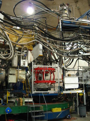
[[Image:IMG 7306.JPG|thumb|Target Coil System in the Hall]] | [[Image:IMG 7306.JPG|thumb|Target Coil System in the Hall]] | ||
| − | Holding field is created | + | Holding field is created by three orthognal [http://en.wikipedia.org/wiki/Helmholtz_coil Helmholtz coils]. As shown here, the small and large coils are creating uniform in horizontal directions and the vertical coils are for a vertical holding field. Since the fields from these three coils are orthognal to each other a Coil System is defined. |
In the configuration of Transveristy experiment, the coil system is rotated 37 degrees from the Hall System. That is small coil pointing to the right downstream of the beam and large coil to the left downstream. | In the configuration of Transveristy experiment, the coil system is rotated 37 degrees from the Hall System. That is small coil pointing to the right downstream of the beam and large coil to the left downstream. | ||
Revision as of 09:24, 17 October 2008
This is to discuss controling holding field of Polarized He3 Target with Helmholtz coils and correction coils.
Contents
Introduction
Holding field is created by three orthognal Helmholtz coils. As shown here, the small and large coils are creating uniform in horizontal directions and the vertical coils are for a vertical holding field. Since the fields from these three coils are orthognal to each other a Coil System is defined.
In the configuration of Transveristy experiment, the coil system is rotated 37 degrees from the Hall System. That is small coil pointing to the right downstream of the beam and large coil to the left downstream.
Characteristics of Hoilding Field Coils
| Coil Name | Radius (m) | Turns | Power Supply | I(A) for 35 G | U(V) for 35 G |
|---|---|---|---|---|---|
| Small | 0.667 | 256 | KEPCO | 10 | 35 |
| Large | 0.758 | 272 | KEPCO | 10 | 35 |
| Vertical | 0.946 | 203 | HP6675A | 18 | 49 |
Coil Current Control
Vertical Coil
Vertical Coil is controlled in constant current mode by Power supply 6675A. In addition, there is a DS345 (GPIB Address 14) providing a control voltage to 6675A. Vertical coil current is baseline current set in 6675A plus a shift proportion to the control voltage.
- 6675A Baseline current is set by GPIB command CURR Base Line Current
- DS345 control voltage is set by GPIB command OFFS Control Setting
A calibration is performed on Sept 23, 2008. With Base Line Current=15A and 16A. Error is on the 0.1% level.
- Base Line Current=15A Result:
     model:
       ''Control Setting''= a + b*''Coil Current''
     Coefficients (with 95% confidence bounds):
       a =      -2.652  (-2.654, -2.651)
       b =      0.1767  (0.1766, 0.1769)
- Base Line Current=16A Result:
     model:
       ''Control Setting''= a + b*''Coil Current''
     Coefficients (with 95% confidence bounds):
       a =      -2.828  (-2.831, -2.826)
       b =      0.1767  (0.1765, 0.1769)
- Further, it's reasonable to a extrapolation by assuming coefficient b in unrelated to Base Line Current:
''Control Setting''= 0.1767*(''Coil Current''-''Base Line Current'')
- According to vertical compass work which was done on Sep 27, to get vertical field, the currents are
     I_v = 16 A
     I_s = -0.370 A
     I_l = 0.345 A
