Difference between revisions of "Details are here"
From Hall A Wiki
(New page: 10:47 2010-05-20 From: Ed Jastrzembski <***@jlab.org> Subject: Re: 150ns deadtime in FADC data triggers? ...) |
|||
| (4 intermediate revisions by the same user not shown) | |||
| Line 1: | Line 1: | ||
| + | <b>Return to [[FADC_DAQ]] wiki</b> | ||
| + | |||
10:47 2010-05-20 | 10:47 2010-05-20 | ||
| + | |||
From: Ed Jastrzembski <***@jlab.org> | From: Ed Jastrzembski <***@jlab.org> | ||
| + | |||
Subject: Re: 150ns deadtime in FADC data triggers? | Subject: Re: 150ns deadtime in FADC data triggers? | ||
| − | To: Brad Sawatzky <***@jlab.org> | + | |
| + | To: Brad Sawatzky <***@jlab.org> | ||
| + | |||
CC: David Abbott <****@jlab.org>, Hai Dong <****@jlab.org> | CC: David Abbott <****@jlab.org>, Hai Dong <****@jlab.org> | ||
| − | I checked on the default values for the internal trigger register and | + | I checked on the default values for the internal trigger register and |
| − | burst guard registers: | + | burst guard registers: |
| − | + | For every internal trigger: | |
| − | For every internal trigger: | + | Trigger width = 48 ns |
| − | Trigger width = 48 ns | + | Hold off after trigger = 40 ns. |
| − | Hold off after trigger = 40 ns. | + | This should give a dead time of 88 ns. However, there may be several 4 |
| − | This should give a dead time of 88 ns. However, there may be several 4 | + | ns clock cycles used to synchronize the communication between my FPGA |
| − | ns clock cycles used to synchronize the communication between my FPGA | + | and Hai's - this will add to the 88 ns.. I'll check on this. |
| − | and Hai's - this will add to the 88 ns.. I'll check on this. | + | |
| − | + | ||
| − | + | ||
| − | + | ||
| − | + | ||
| − | + | ||
| − | + | ||
| + | If the burst guard is enabled (default values may be loaded by writing | ||
| + | a '1' to bit 17 of the RESET register): | ||
| + | A total of 5 triggers are allowed to occur within any 2048 ns window. | ||
| + | If more triggers than this occurs, a dead time of 8192 ns is forced so | ||
| + | that the internal pipelines will not overflow. | ||
| − | + | On Thu, 20 May 2010, Ed Jastrzembski wrote: | |
This dead time does not apply to the scalers. - Ed J. | This dead time does not apply to the scalers. - Ed J. | ||
| − | + | On Thu, 20 May 2010, David Abbott wrote: | |
| − | + | There is a minimum time the FADC needs to "accept" and buffer one | |
| − | + | trigger for processing. This is as I recall about 70-80ns. This is | |
| − | + | true regardless of whether the trigger is external or internally | |
| − | + | generated. | |
| − | + | Now there are certain controls we have provided for the internal | |
| − | + | trigger (widths and delays like you would have with NIM electronics) | |
| − | + | so that you can have some control these triggers. | |
| − | + | There is one general register (itrig_cfg) which takes two 16 bit | |
| − | + | parameters - width and holdoff (in clock ticks - 4ns/tick) that | |
| − | + | define the width of the internal trigger pulse and then a deadtime | |
| − | + | before the FADC will accept another. The sum of these two values | |
| − | + | will define the trigger deadtime for the FADC. | |
| − | + | I believe this register comes programmed with default values. Ed | |
| − | + | would know what they are. but 150 ns sounds like it would be about | |
| − | + | right. In practice the sum of these two cannot be less than 80ns or | |
| − | + | the FADC will choke in some strange ways... | |
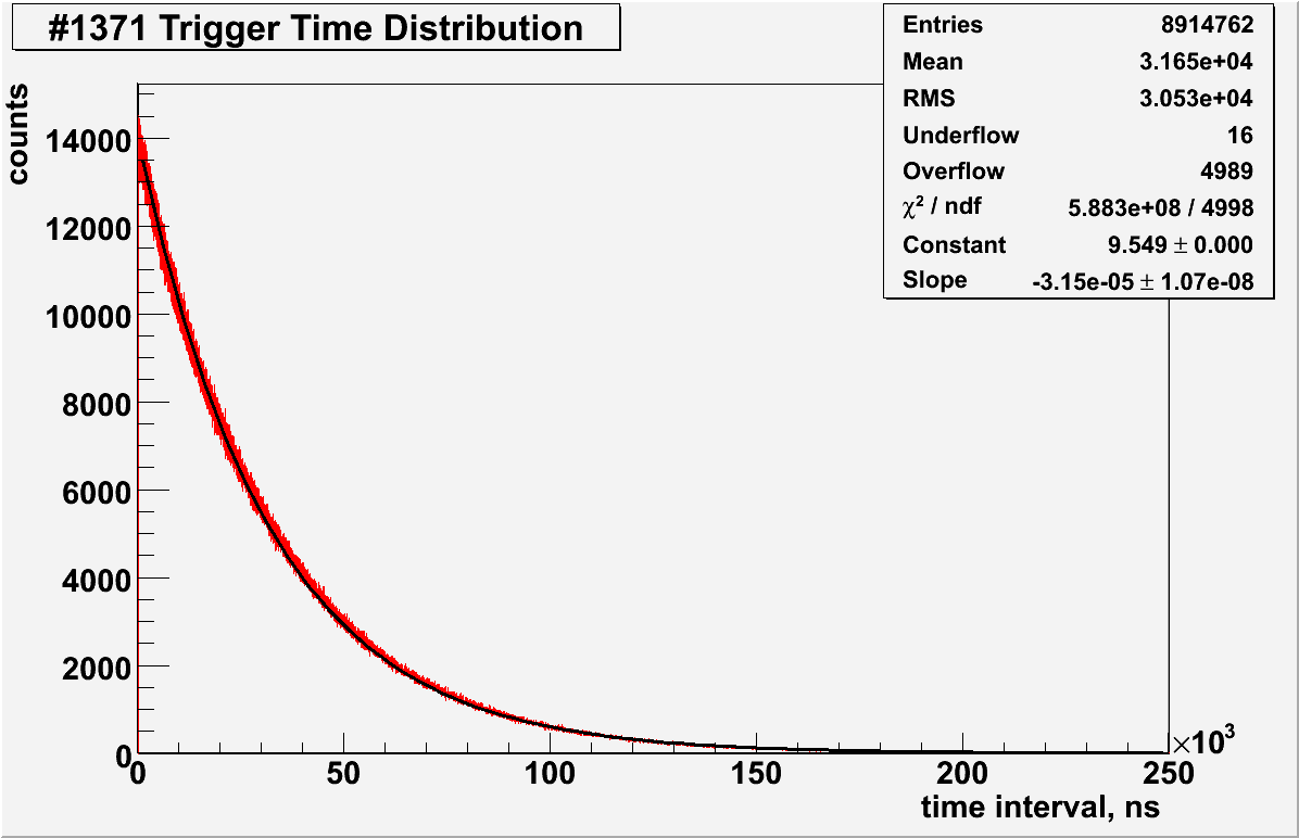
| − | + | *[http://hallaweb.jlab.org/equipment/moller//wiki/fadc/plots/TrigTime1371.png Trigger time distribution for run# 1371 ] | |
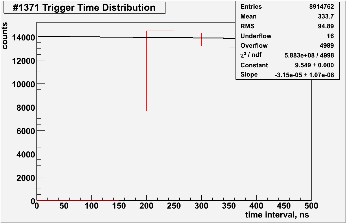
| − | + | *[http://hallaweb.jlab.org/equipment/moller//wiki/fadc/plots/TrigTime1371_d.png zoomed ] | |
Latest revision as of 16:26, 22 November 2016
Return to FADC_DAQ wiki
10:47 2010-05-20
From: Ed Jastrzembski <***@jlab.org>
Subject: Re: 150ns deadtime in FADC data triggers?
To: Brad Sawatzky <***@jlab.org>
CC: David Abbott <****@jlab.org>, Hai Dong <****@jlab.org>
I checked on the default values for the internal trigger register and
burst guard registers:
For every internal trigger:
 Trigger width = 48 ns
 Hold off after trigger = 40 ns.
 This should give a dead time of 88 ns. However, there may be several 4
 ns clock cycles used to synchronize the communication between my FPGA
 and Hai's - this will add to the 88 ns.. I'll check on this.

If the burst guard is enabled (default values may be loaded by writing
a '1' to bit 17 of the RESET register):
A total of 5 triggers are allowed to occur within any 2048 ns window.
If more triggers than this occurs, a dead time of 8192 ns is forced so
that the internal pipelines will not overflow.
On Thu, 20 May 2010, Ed Jastrzembski wrote:
This dead time does not apply to the scalers. - Ed J.
On Thu, 20 May 2010, David Abbott wrote:
There is a minimum time the FADC needs to "accept" and buffer one
trigger for processing. This is as I recall about 70-80ns. This is
true regardless of whether the trigger is external or internally
generated.
Now there are certain controls we have provided for the internal
trigger (widths and delays like you would have with NIM electronics)
so that you can have some control these triggers.
There is one general register (itrig_cfg) which takes two 16 bit
parameters - width and holdoff (in clock ticks - 4ns/tick) that
define the width of the internal trigger pulse and then a deadtime
before the FADC will accept another. The sum of these two values
will define the trigger deadtime for the FADC.
I believe this register comes programmed with default values. Ed
would know what they are. but 150 ns sounds like it would be about
right. In practice the sum of these two cannot be less than 80ns or
the FADC will choke in some strange ways...