Difference between revisions of "Baffle Design"
| Line 4: | Line 4: | ||
| − | [[Image:Fitpaths.png| | + | [[Image:Fitpaths.png|200px|thumb|Fitting trajectory paths]] |
| + | [[Image:CLEOpaths.png|200px|thumb|CLEO Baffle openings (before introduction of wedge)]] | ||
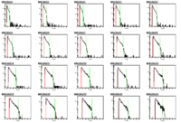
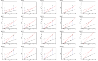
| + | We define as fixed number of blocks which expand over a radius that will accept the full angular range from the whole target. Each block then has a range in phi, which we fit shown in the figture. | ||
| − | + | [[Image:Design desc.png|500px|Designing baffle openings]] | |
| − | + | ||
| − | [[Image:Design desc.png|500px | + | |
These are then considered, for each block over all baffles, to carve out an opening which does not allow particles below a momentum from making it through. There is a maximum opening which is defined from the number of sectors, along with a minimum "dead zone" which prevents photons. | These are then considered, for each block over all baffles, to carve out an opening which does not allow particles below a momentum from making it through. There is a maximum opening which is defined from the number of sectors, along with a minimum "dead zone" which prevents photons. | ||
| − | |||
| − | |||
==First order efficiency curves== | ==First order efficiency curves== | ||
| Line 43: | Line 41: | ||
|} | |} | ||
| − | [[Image:Bafflenaiveeff.png]] | + | [[Image:Bafflenaiveeff.png|500px]] |
It is important to note the <math>\epsilon_{max}</math> is proportional to the field integral. | It is important to note the <math>\epsilon_{max}</math> is proportional to the field integral. | ||
| Line 69: | Line 67: | ||
[[Solid Baffle | Zhiwen's Evaluation of Eugene's Baffles in GEMC]] | [[Solid Baffle | Zhiwen's Evaluation of Eugene's Baffles in GEMC]] | ||
| + | Note: These are based on an incorrect implementation | ||
Revision as of 12:02, 24 September 2012
Contents
Baffles Design
Designing baffles from ray traces requires GEMC runs without baffles, but detectors at the baffle z positions.
We define as fixed number of blocks which expand over a radius that will accept the full angular range from the whole target. Each block then has a range in phi, which we fit shown in the figture.
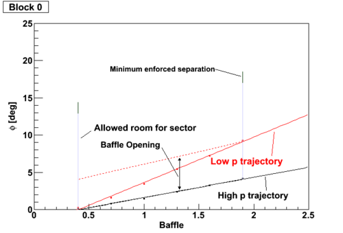
These are then considered, for each block over all baffles, to carve out an opening which does not allow particles below a momentum from making it through. There is a maximum opening which is defined from the number of sectors, along with a minimum "dead zone" which prevents photons.
First order efficiency curves
The efficiency can be estimated by considering the simple geometric arguments above, the two defining low and high momenta <math>p_{l}</math> and <math>p_{h}</math>, a maximum efficiency based on opening width (based on <math>p_{h}</math>) and number of sectors <math>n_{s}</math>, and a constant proportional to the field integral, <math>c_{Bdl}</math>.
The overall maximum efficiency is
<math>\epsilon_{max} = \frac{c_{Bdl} n_s}{2\pi p_{h}}</math>
Using one intermediate momentum <math>p_m</math> defined by
<math> p_m = \left( 1/p_{l} - 1/p_{h} \right)^{-1}</math>
there is an efficiency curve described by the piecewise function
| <math> p < p_l </math>: | <math>\epsilon = 0</math> |
| <math> p_l <p < p_m </math>: | <math> \epsilon_{max} \left(1+\frac{p_h}{p_m} - \frac{p_h}{p}\right) </math>: |
| <math> p_m < p < p_h </math>: | <math> \epsilon_{max}</math> |
| <math> p_h < p </math>: | <math> \epsilon_{max}\frac{p_h}{p}</math> |
It is important to note the <math>\epsilon_{max}</math> is proportional to the field integral.
Older Baffle Comparisons
Seamus' Baffle Comparisons
| Eugene's BaBar Design in GEMC | [1] |
| Eugene's for Other Magnets | [2] |
| Basic New Designs | [3] |
| New design from ray tracing | [4] |
Eugene's Baffles
Zhiwen's Evaluation of Eugene's Baffles in GEMC Note: These are based on an incorrect implementation


