Difference between revisions of "Oven Control"
(→PID Parameters for CN77544-C2 Controller) |
(→Setpoints) |
||
| Line 142: | Line 142: | ||
# Either change the next setpoint or press '''SETPTS''' several times until you see '''RUN''' and then the meter should turn to the normal reading mode. | # Either change the next setpoint or press '''SETPTS''' several times until you see '''RUN''' and then the meter should turn to the normal reading mode. | ||
| + | === Calibration @ Mar 9, 2010 === | ||
| + | |||
| + | Air flow meter in oven control chassis is cross calibrated with mechanical air flow meter at target. | ||
| + | |||
| + | {| class="wikitable" border="1" | ||
| + | |- | ||
| + | ! Mechanical Flow Meter | ||
| + | ! Digital Flow Meter | ||
| + | |- | ||
| + | | 1 | ||
| + | | 260 | ||
| + | |- | ||
| + | | 3 | ||
| + | | 390 | ||
| + | |- | ||
| + | | 5 | ||
| + | | 490 | ||
| + | |- | ||
| + | | 7 | ||
| + | | 600 | ||
| + | |} | ||
| + | |||
| + | Alarm 4 is set at 280. | ||
== Heater Temperature Meter == | == Heater Temperature Meter == | ||
Revision as of 19:13, 9 March 2010
Contents
Introduction
The air flow used by the oven is pressurized dry and filtered air at room temperature is provided by a dedicated compressor in the Hall. The air enters the system through a shut-off valve and a pressure regulator, which is typically set to an output pressure of 15 psi (knot 6). The flow rate is measured with a gas velocity sensor (Omega model FMA-905) connected to a display unit (Omega DP41-E-S2R) on the left side of the control box that provides an alarm to indicate insufficient flow. The air then passes through two resistive heaters (120 VAC, 1200 W) and continues through insulated copper tubing into the target oven. The oven material is ceramic which can withstand a temperature of at least 300C continuously. The air finally exits the system through an exhaust pipe where it can cool down. Both inlet and exhaust pipes are inside the oven supporting tube filled with insulation material.
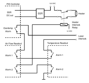
A 100Pt RTD (Omega model F3105) measures the temperature inside the oven. A process controller (Omega CN77540-C2) sitting in the middle of the control box operating in PID mode drives the heater via a solid-state relay (SSR) box regulating one of the heater power dependent on the temperature detected by the RTD. Another heater stays on all the time and can be adjusted by a variac located in the Hall. The SSR (Omega model SSR240DC10) accepts a low-voltage (3 − 32 VDC) control signal of about 30 mA. Mechanical relays between the SSR and the heater allows interruption of both 120 VAC heaters' power in case of a malfunction.
A thermocouple (Omega 5SC-GG-K-30-36) is mounted on the tubing right after the heater to allow monitoring of the temperature of the air exiting the heater. Another display unit (Omega DP41-TC-S2R) on the right side of the control box reads the thermocouple and generates an alarm if the temperature exceeds a preset threshold.
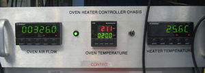
The PID controller as well as the two display units are installed in a 19” chassis in the electronics racks on the second floor of the counting house where they can be manually operated if necessary. All other components are located in the Hall in the vicinity of the target. The instruments can be monitored and programmed remotely via serial RS-232 communications, which allows convenient control via an EPICS/MEDM graphical user interface (GUI) in the counting house (Not working at this moment).
Oven Temperature Control
Now the oven temperature is controlled through EPICS. Find the oven
control from the same menu of laser control and ladder control, then
type in the temperature setpoint and hit enter key. You should be
able to see the setpoint changed to new value after a second or two.
The middle temperature meter is controlling the second heater of the series while the first one is working in the constant mode set by a variac. The lower line of the meter showing the current set temperature of the oven and the upper line is the read back of the RTD. A flashing/steady yellow sp1 shown on the left side of the meter is a indicator of that the second heater is activated by the controller. To change the temperature setpoint, do the following:
- Press MENU button to enter setpoint 1 editing mode, you will see both SP1 and the send line are flashing;
- Press >/MIN to change digit;
- Press ^/MAX to change the value of the flashing digit;
- Repeat step 2 and 3 to complete the input of new setpoint value;
- Press ENTER button to store the new setpoint, you should see RUN in the bottom line and then the new setpoint value.
PID Parameters for CN77544-C2 Controller
Output Redirection
- S1.o1
Input
- Input Type: RTD
- RTD Type: 392.3
- RTD Value: 100_
RDG Configuration
- Decimal Point: FFF.F
- Temperature Units: C
- Filter Constant: 0004
Alarm 1
- Alarm: Enabled
- Type: Absolute
- Latched: Unlatched
- Contact: n.c.
- Setup: Below
- Power ON: Enabled
- Low Value: 210
- High Value: (anything)
Alarm 2
- Not installed
Loop Break
- Disabled
Output1
- Self: Disable
- % Low: 0000
- % High: 0099
- Control Type: PID
- Action Type: Reverse
- Auto PID: Enabled
- Adaptive Control: Disabled
- Anti Integral: Enabled
- Proportional Band (P): 1000
- Reset Setup (I): 3999
- Rate Setup (D): 0
- Cycle Time: 0007
- Damping Factor: 0003
Output2
- (anything)
Ramp&Soak
- Disabled
Analog Output
- Not installed
Communication Option
- Baud: 9600
- Parity: Odd
- Data Bits: 8bit
- Stop Bits: 1bit
Bus Format
- Checksum: no
- Line Feed: no
- Echo: no
- Standard: 232C
- Mode: Command
- Separator: Space
Data Format
- Status: no
- Reading: yes
- Peak: no
- Valley: no
- Unit: no
- ID: no
Address Setup
- 0001
Transmit Time
- 0016
Oven Air Flow Meter
Alarms
- Alarm 1 of the meter is used to interlock lasers
- Alarm 2 interlocks both heaters.
The alarm will be triggered if the airflow is less than certain thresholds.
If Alarm 1 is triggered, a red 3 will be shown in the meter below the readings,
and Alarm 2 will show a red 4 as in the control box picture.
Setpoints
Both Alarm 1 and Alarm 2's thresholds are in deviation mode, the 4 setpoints of the meter are set as following:
- Setpoint 1 and Setpoint 2 of this meter should always be set to 0;
- Setpoint 3 is the threshold for Alarm 1;
- Setpoint 4 is the threshold for Alarm 2.
To check/change Setpoints, do the following steps:
- Press SETPTS several times until the wanted setpoint showing up;
- Use >/MIN button to change digit;
- Use ^/MAX button to modify the value of the flashing digit;
- Repeat step 2 and 3 to complete the input of new setpoint value;
- Press SETPTS to store the new value to the meter, you should see STORED shown on the display and the next setpoint will be shown;
- Either change the next setpoint or press SETPTS several times until you see RUN and then the meter should turn to the normal reading mode.
Calibration @ Mar 9, 2010
Air flow meter in oven control chassis is cross calibrated with mechanical air flow meter at target.
| Mechanical Flow Meter | Digital Flow Meter |
|---|---|
| 1 | 260 |
| 3 | 390 |
| 5 | 490 |
| 7 | 600 |
Alarm 4 is set at 280.
Heater Temperature Meter
Alarms
As oven air flow meter
- Alarm 1 of the meter is used to interlock lasers
- Alarm 2 interlocks both heaters.
The alarm will be triggered if the heater temperature is higher than certain thresholds.
If Alarm 1 is triggered, a red 3 will be shown in the meter below the readings,
and Alarm 2 will show a red 4 as in the control box picture.
Setpoints
The ways to set the setpoints of the heater temperate meter is exactly the same of setting the air flow meter.


