Left HRS Scintillator Timing
Contents
Initial Time Offset Calibration
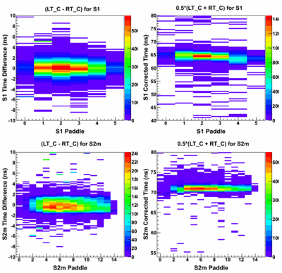
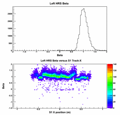
S1 and S2m time difference and corrected time plots for run 2512 after initial time offset calibration:
The left figure shows that the time differences are fairly well calibrated, but the corrected times show some shifts
for a few paddles in S1 and S2m. The beta spectrum shows some discontinuities that I thought might be related to
the time offset shifts. I will present more on this in the discussion below. The beta spectrum has a long tail for beta greater than 1, and the beta resolution is about 0.14.
Second Iteration
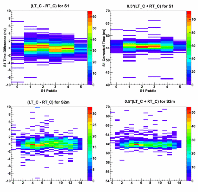
For the second iteration, I decided to look at a recent production run: 3789.
In this iteration, I fine-tuned the time offsets to improve the corrected time between paddles to remove the remaining
shifts from the previous iteration. The figures on the left show the time versus paddle for S1 and S2m are now
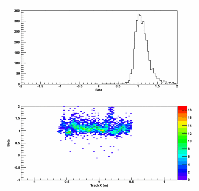
much improved over the first iteration. The resolution of the beta spectrum has improved to about 0.116.
However, we still see that the resolution in beta is limited by the discontinuities seen in the beta versus track x
plot.
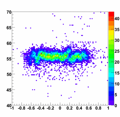
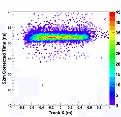
At this point, I was puzzled by these discontinuities and decided to look at the S1 and S2m corrected times versus the track x position.
The left plot (unfortunately not labeled) and the right plot show the corrected S1 and S2m times, respectively. The discontinuities seen in the beta spectrum are clearly due to the problems seen in the S1 spectra. The timing from S2m is very good and has sub-nanosecond resolution already.
Scintillator Timing Resolutions (at this point)
The following figure shows the S1 and S2m timing resolution with time offset corrections. The S1 resolution is about 1.05 ns, and the S2m resolution is 640 ps. With more fine tuning and adding the time-walk corrections, the S2m time resolution should get better. Until the S1 problem is fixed, it will remain above 1 ns.
S1 Timing Distribution
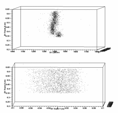
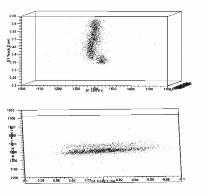
The two distinct timing shifts seen in the S1 scintillator are isolated to the second and fifth paddles. In an attempt to understand the problem, I looked at the timing from these paddles versus the track X and Y positions projected to the scintillator plane. I found that the timing difference was in the raw TDC histograms, so the following plots show the S1 left PMT #5 (index 4) raw TDC channels versus S1 track x and y.
