SIDIS/PVDIS Cherenkov
Contents
Tuesday 9/10/13
Some comparisons with the latest baffle design (tentatively named "more1"), and how it is different than the precious design with less baffles but an inner radius for the first baffle of 5cm.
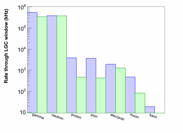
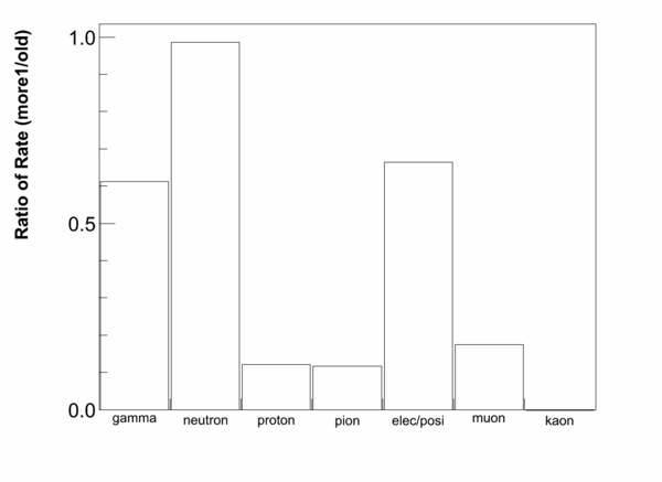
Comparison of total rate through cherenkov window:
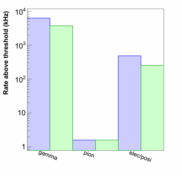
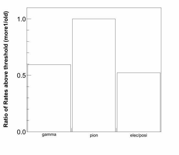
A comparison of PMT rates (> 1 pe) for the newer and older designs:
| Previous Baffle (MHz) | "More1" (MHz) | |
|---|---|---|
| 1 or more pe's per sector | 4.94 | 2.99 |
| 2 or more pe's per sector | 3.44 | 1.93 |
| 1 or more pe's in two different PMTs | 2.50 | 1.56 |
Tuesday 8/6/13
Baffle inner radius at 5cm / no beam line shield / no absorber.
Total statistics:
95 out of 2e8 events have at least 1 photoelectron.
64 / 95 come from electrons/positrons (0 / 95 come from leptons with less than 10 MeV Energy)
5 / 95 come from pions
the remaining 26 are still a ??
Friday 7/26/13
I've completed a new study of the low energy background's effect on the LGC rate.
Initial results
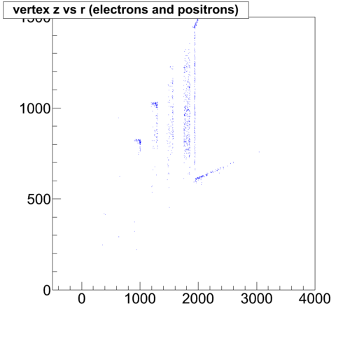
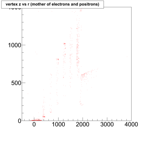
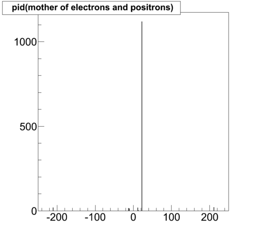
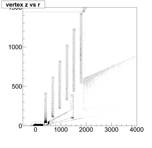
We have in this case the PVDIS baffles (with a 4cm inner radius at the first baffle), the standard exit beampipe, and the tungsten absorber. Electrons produced from the low energy photons seem to be the primary source of background signal. The Z-R spectra of photon events that cross the Cherenkov window are:
Notice most events come from the inner radius of the first baffle and the front of the absorber.
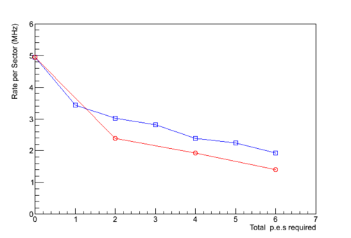
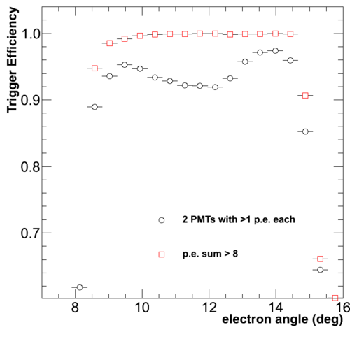
For this configuration, my calculated rate WITH NO TRIGGER CUTS is 61 MHz per sector (or 61/9 = 6.8 MHz per PMT). If we put a low-level trigger to restrict us to 2 or more photo-electrons per sector, the rate drops to 33 MHz per sector (or 3.6 MHz per PMT). There are many logical combinations for triggers, but another example is to have at least 2 PMTs fire per sector, each with at least 2 photo-electrons; in this case the rate drops to 22 MHz per sector (2.5 MHz per PMT).
I've started running new events with a larger inner radius for the first baffle (5cm as opposed to 4cm), also with no absorber or exit beampipe. I'll post resulst as soon as I have them.
Tuesday 6/24/13
A look at the trigger efficiencies for one PMT sum vs multi-pmt.
Tuesday 4/30/13
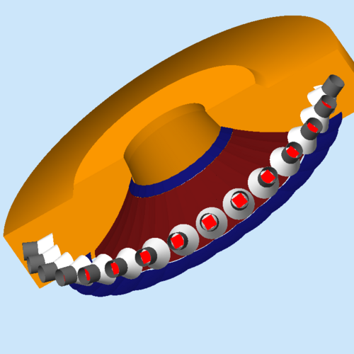
To expand to lower angles of SIDIS coverage, an additional 3rd mirror was added to the simulation.
- Details and concerns:
- The middle set of mirrors share the overlap coverage of PVDIS 22-33 deg and SIDIS 8-15 deg, The PVDIS angles > 33 deg are handled by the outermost of mirrors, and the SIDIS angles from 7-8 deg are handled by the innermost set of mirrors.
- This is needed if we want to incline the middle mirror for use in both SIDIS and PVDIS.
- The middle mirror quickly looses efficiency due to a reflection offset for SIDIS low angles. This is due to the size of the mirror and an inefficiency of a simple spherical mirror to uniformly reflect the incident rays onto the PMT face, due to the transport of the radiating particle in the magnetic field.
- The new set of mirrors sits unrealistically close to the border of the tank. Would probably need to extend tank or reduce angle coverage of mirrors.
- If we wanted SIDIS < 7 deg, we would need to not only change the diameter of the snout, but also adjust the winston cones between SIDIS and PVDIS configurations; the cones aren't wide enough to accept SIDS < 7 deg and PVDIS > 34 deg simultaneously.
- The middle set of mirrors share the overlap coverage of PVDIS 22-33 deg and SIDIS 8-15 deg, The PVDIS angles > 33 deg are handled by the outermost of mirrors, and the SIDIS angles from 7-8 deg are handled by the innermost set of mirrors.
- Some possibilities:
- Redesign for a larger inner most and smaller middle mirror, have both mirrors incline when switching to PVDIS.
- Expected result: larger SIDIS p.e.'s at small angles, less PVDIS p.e.'s at small angles.
- Redisign for separate mirrors and cone positions for PVDIS and SIDIS:
- Expected result: Better overall acceptance at edges (small angle / large angle). Large increase in mirror cost and difficulties in tank design.
- Redesign for a larger inner most and smaller middle mirror, have both mirrors incline when switching to PVDIS.
