File list
From Hall A Wiki
This special page shows all uploaded files.
| Date | Name | Thumbnail | Size | Description | Versions |
|---|---|---|---|---|---|
| 11:28, 10 April 2012 | 3D-prototype-1-inch.jpg (file) |  |
11 KB | 3D view of conceptual design of a possible Be window | 1 |
| 21:30, 3 April 2012 | Be-window-prototype UVa 1-inch 10feb2011.pdf (file) | 4 KB | Rough sample prototype drawing for a possible beryllium window end cap assembly for future polarized helium-3 gas targets. | 1 | |
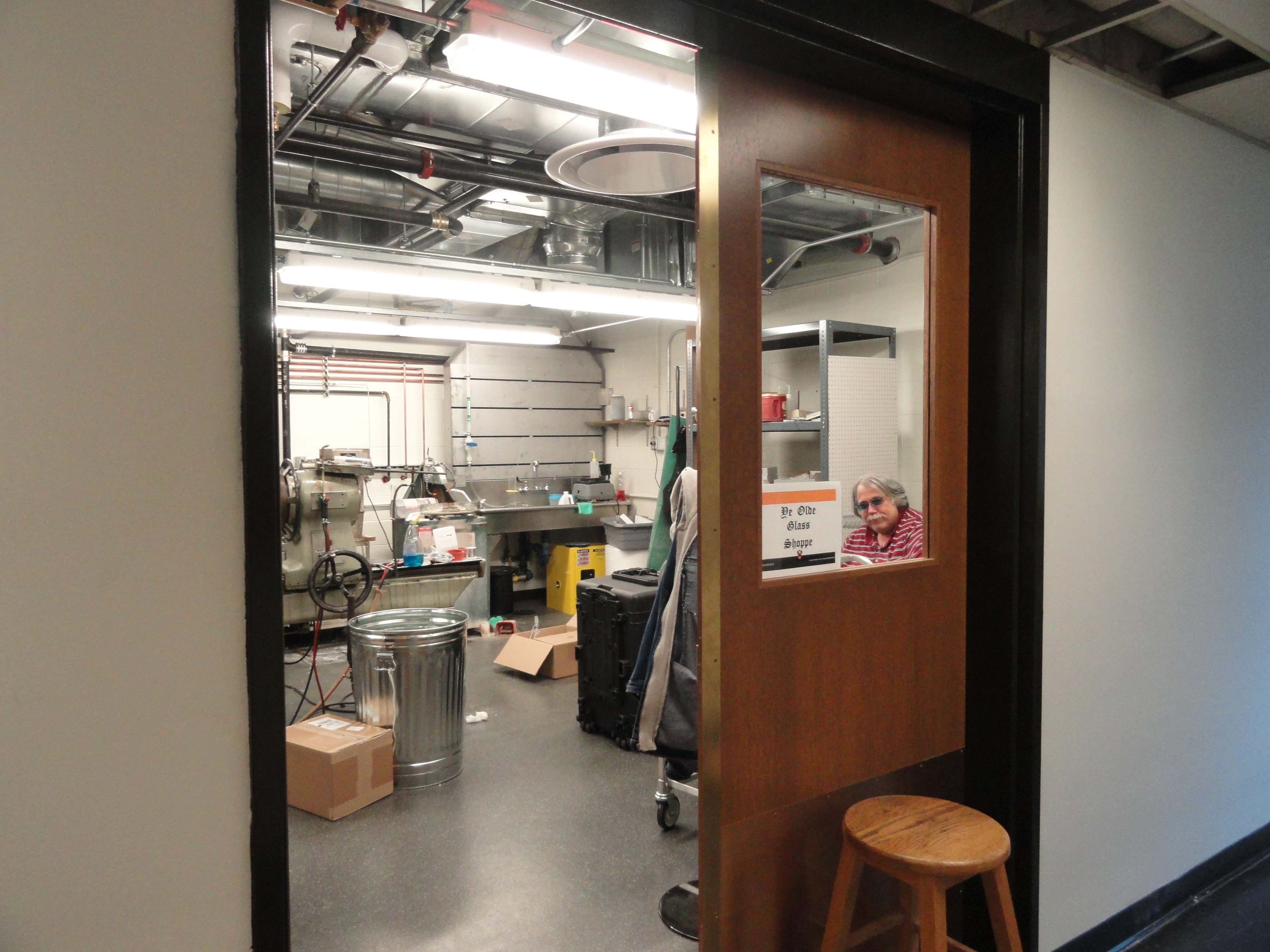
| 17:21, 27 December 2011 | Souza glass shop02 27dec2011.jpg (file) |  |
3.78 MB | Princeton Glass Shop in Jadwin Rm. 123 Winter 2011, with Mike Souza seen through the window. | 1 |
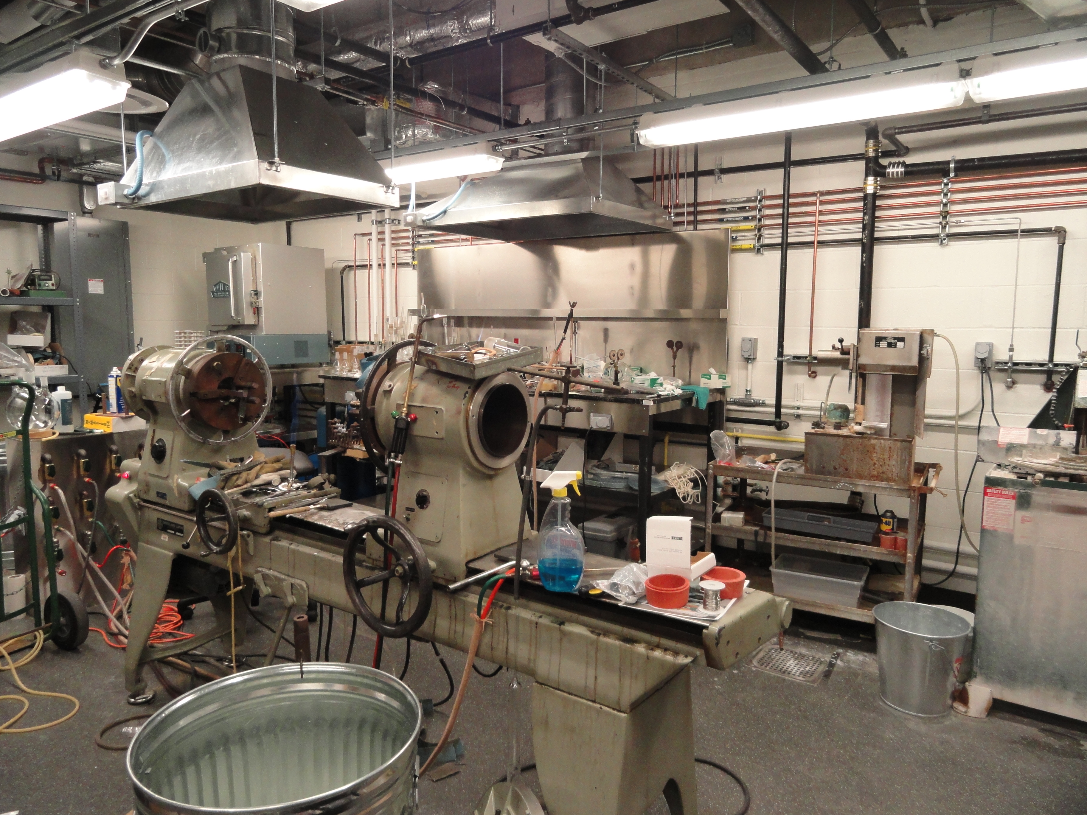
| 17:19, 27 December 2011 | Souza glass shop01 27dec2011.jpg (file) |  |
4.14 MB | Princeton Glass Shop in Jadwin Rm. 123 Winter 2011 | 1 |
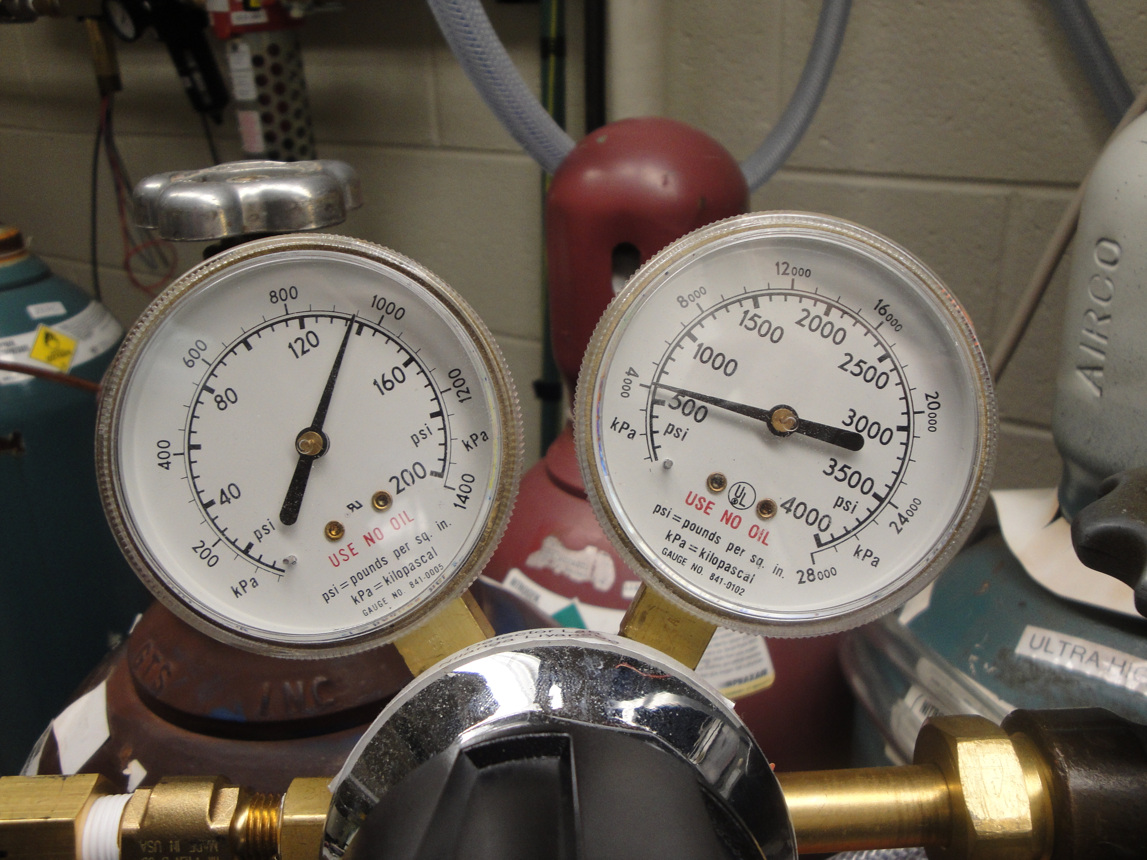
| 19:22, 29 November 2011 | Ptest9 cp-100-T 17nov2011.jpg (file) |  |
4.83 MB | Regulator gauges: Right to left: Tank pressure P=600psig. Output pressure P=137psig. | 1 |
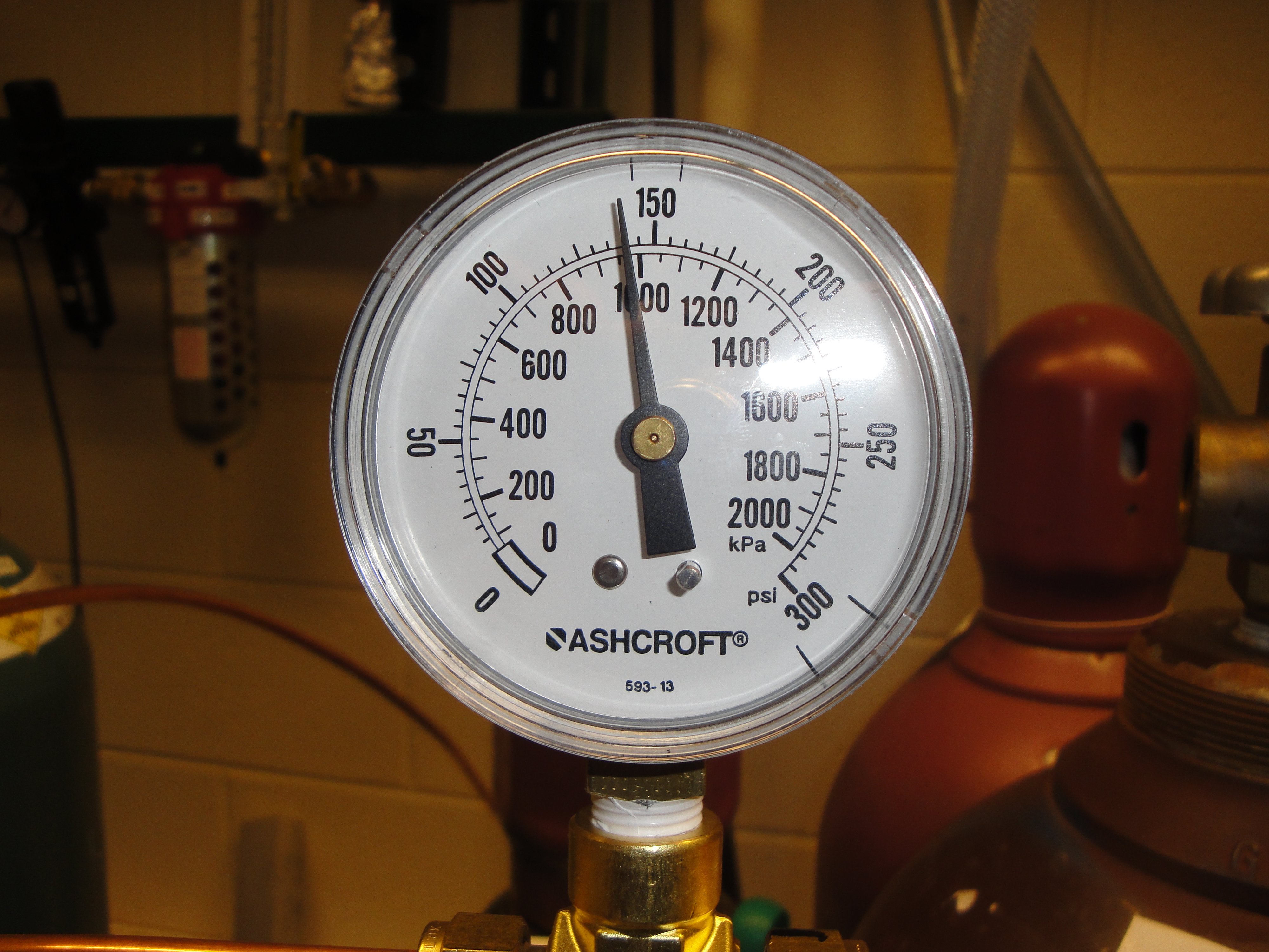
| 19:18, 29 November 2011 | Ptest8 cp-100-T 17nov2011.jpg (file) |  |
4.54 MB | Test pressure gauge P=140psig. | 1 |
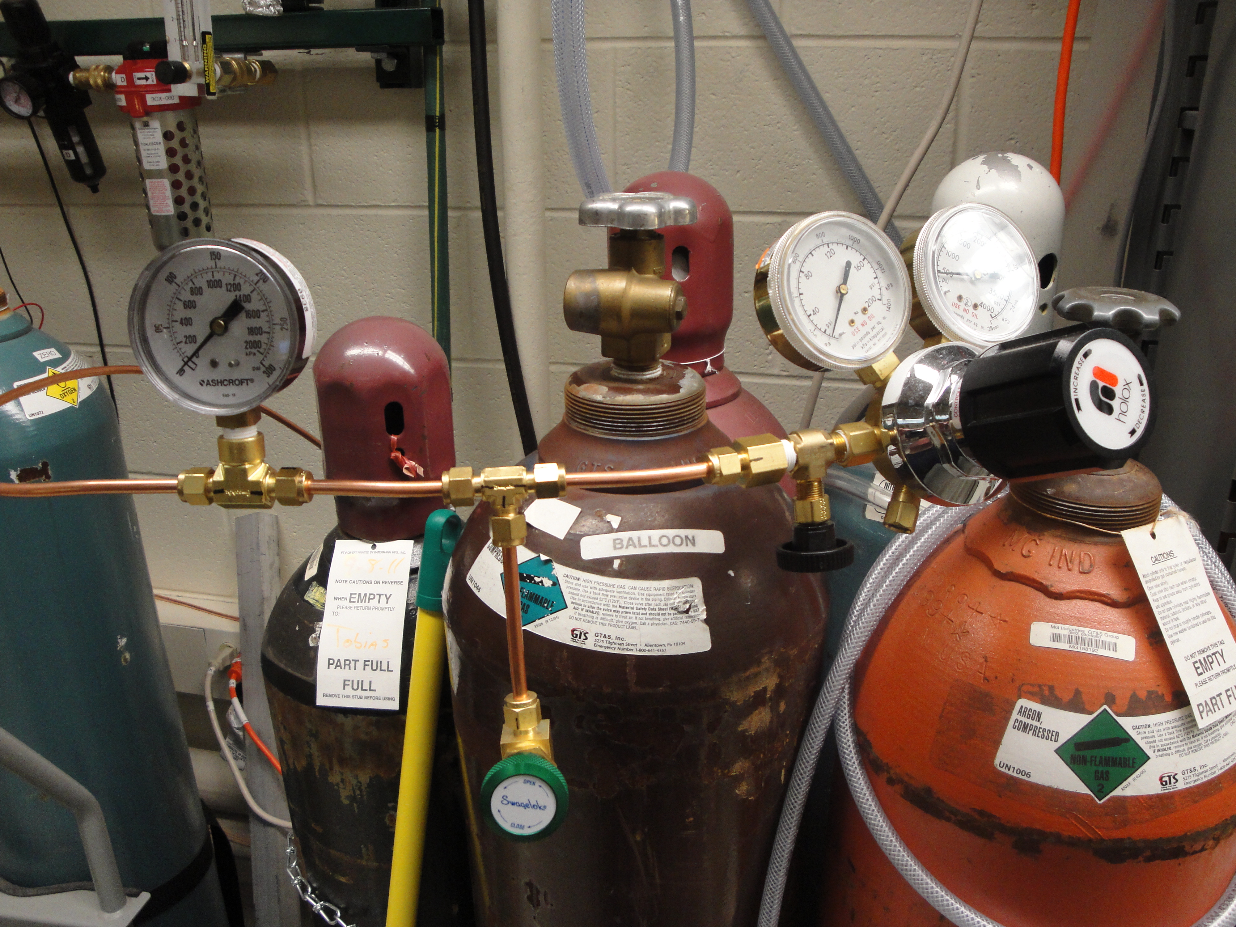
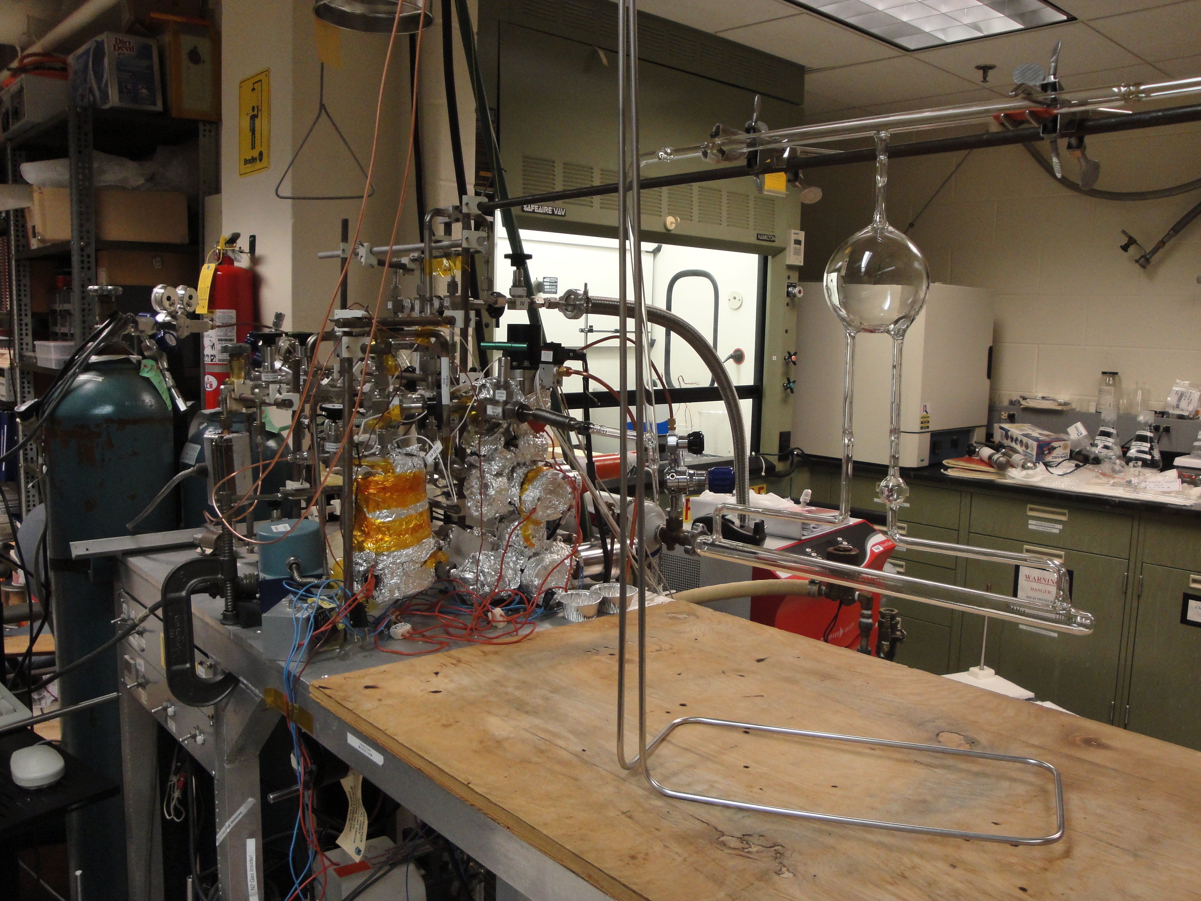
| 19:14, 29 November 2011 | Ptest7 cp-100-T 16nov2011.jpg (file) |  |
4.87 MB | High pressure gas delivery plumbing for test setup @ UVa. Right to left: Regulator tank gauge, output gauge, shutoff valve. Nupro pressure relief valve. Test pressure gauge. | 1 |
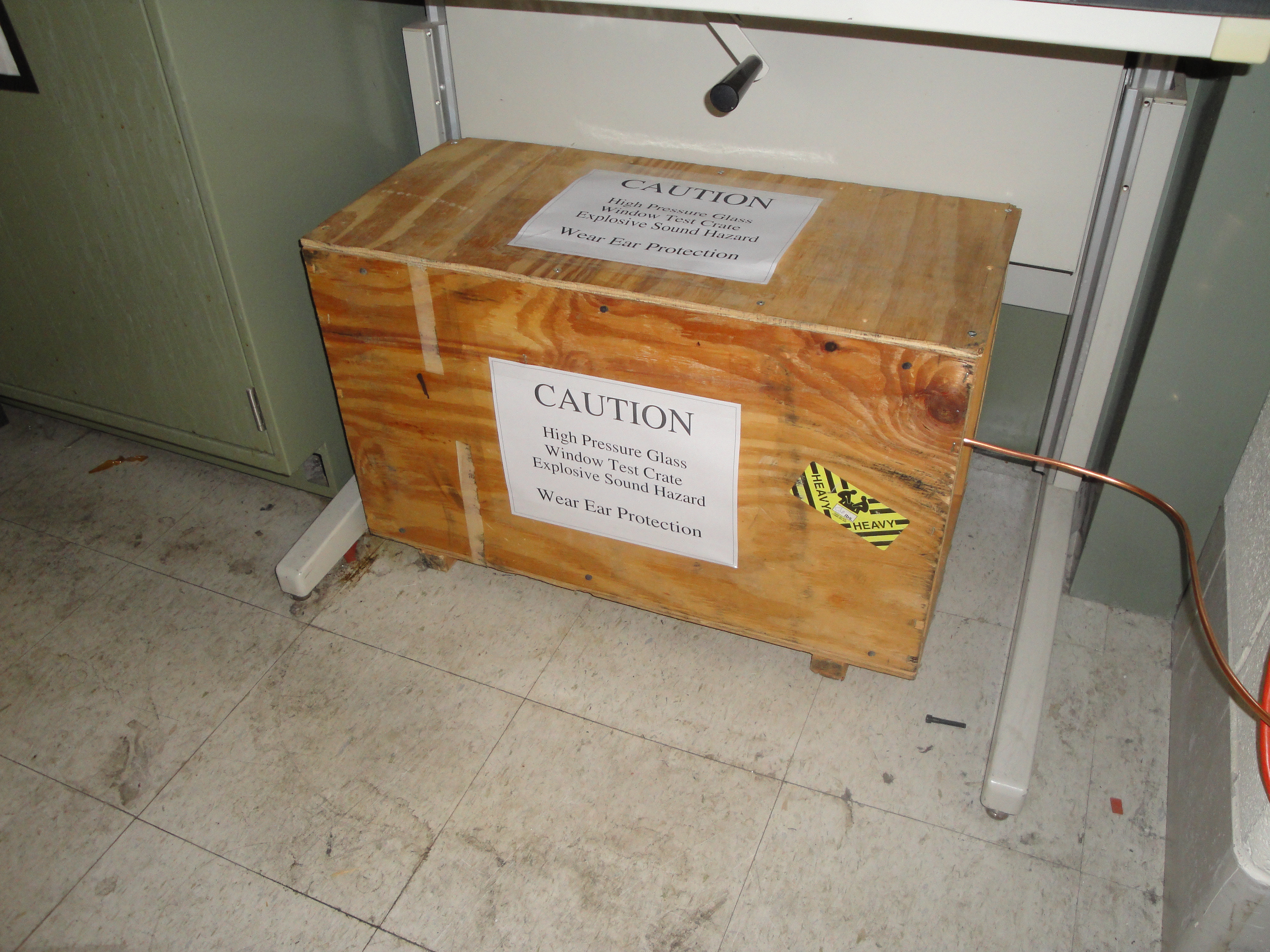
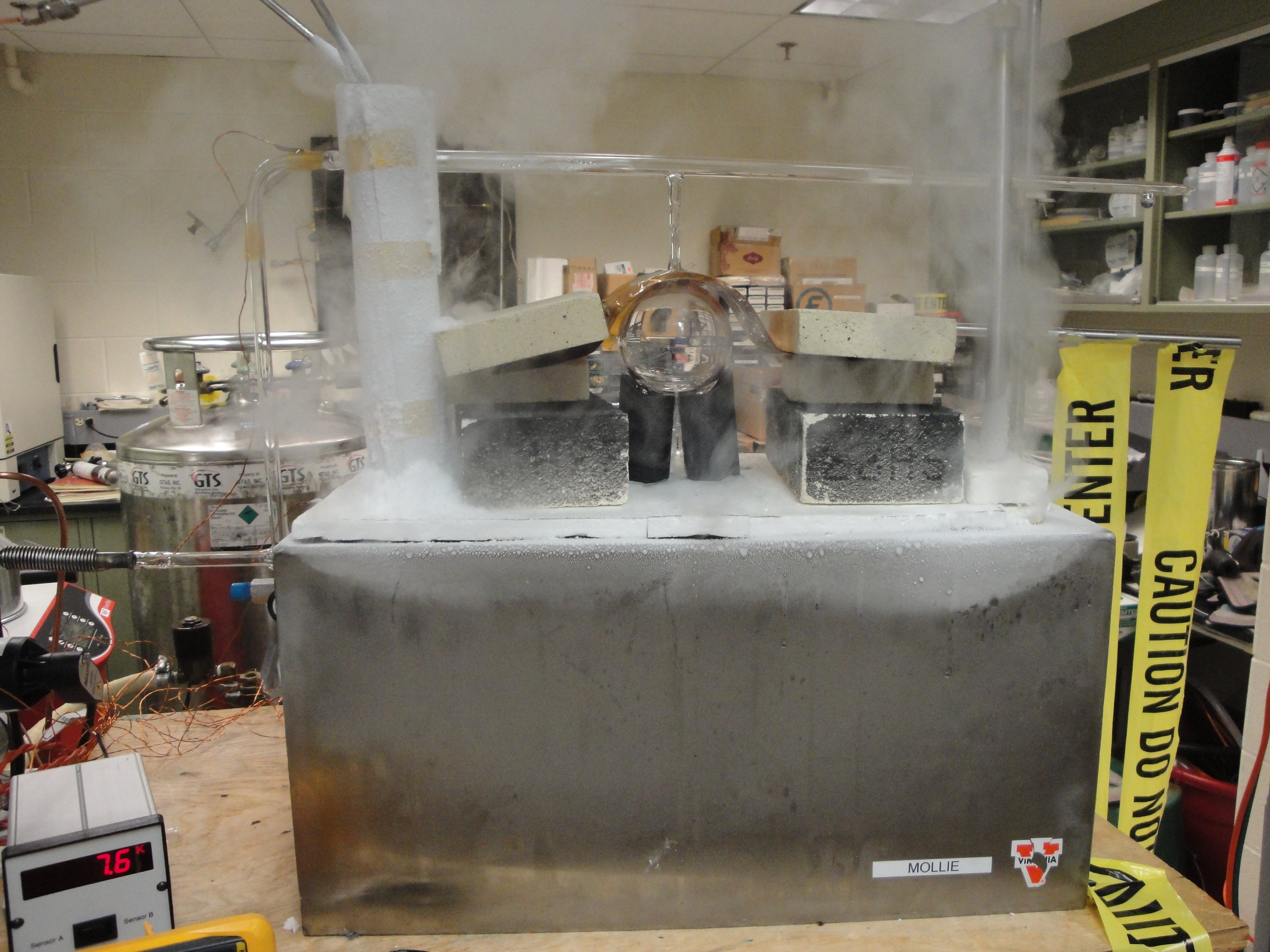
| 19:08, 29 November 2011 | Ptest6 cp-100-T 16nov2011.jpg (file) |  |
4.67 MB | Pressure test setup @ UVa for target windows blocked with protective wall and caution signs. | 1 |
| 19:03, 29 November 2011 | Ptest5 cp-100-T 16nov2011.jpg (file) |  |
4.78 MB | Pressure test setup @ UVa for target windows. Crate is fully closed. | 1 |
| 19:00, 29 November 2011 | Ptest4 cp-100-T 16nov2011.jpg (file) |  |
4.84 MB | Top view of pressure test setup at UVa for target windows with both cardboard boxes closed and weighed down with two half-thick fire bricks on top. | 1 |
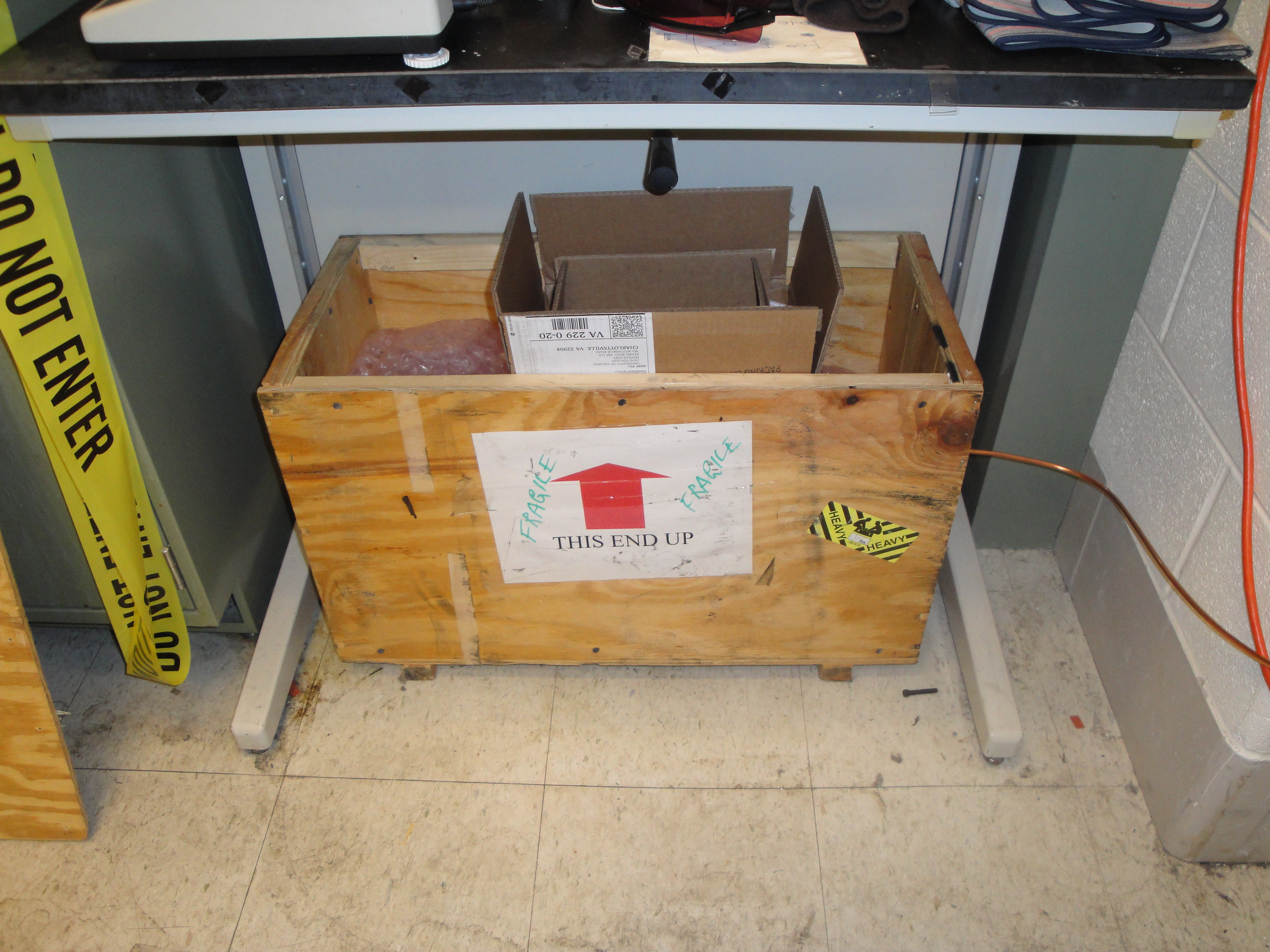
| 18:55, 29 November 2011 | Ptest3 cp-100-T 16nov2011.jpg (file) |  |
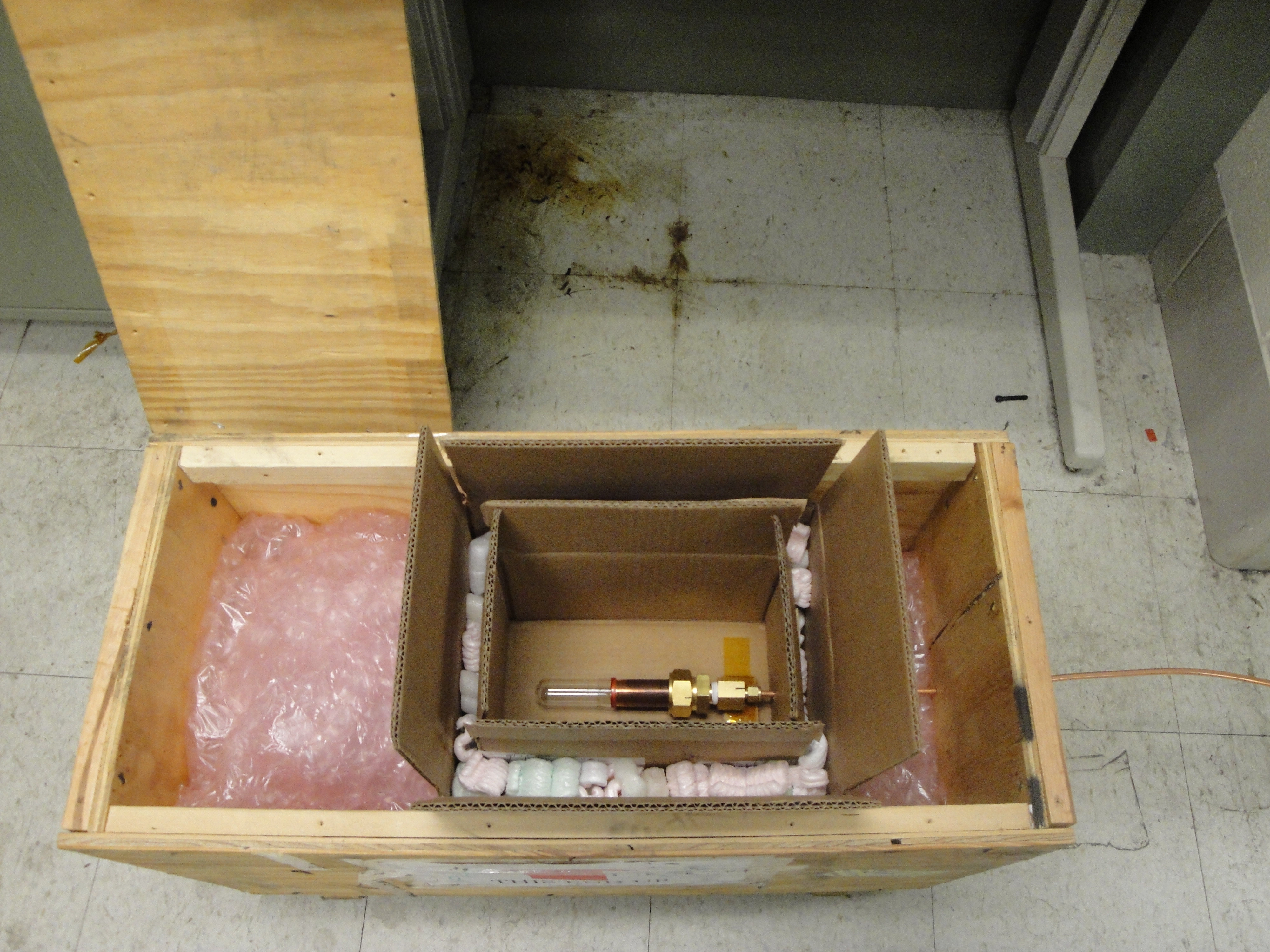
4.83 MB | Side view of pressure test setup for target windows, cardboard boxes and crate lid are open. | 1 |
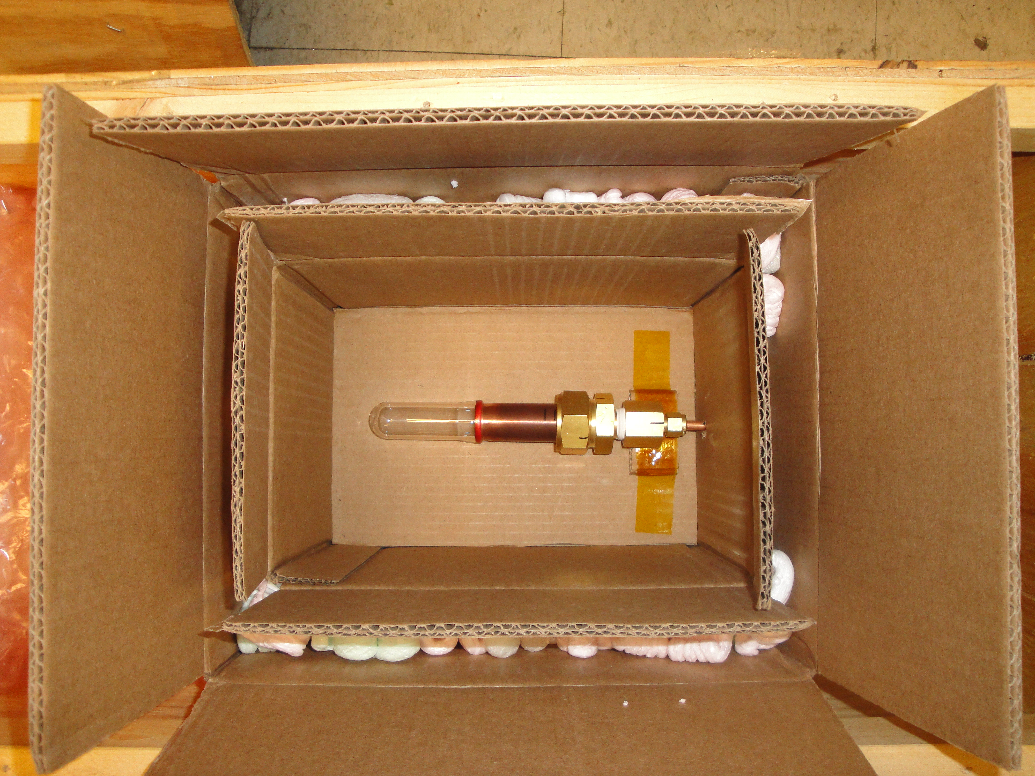
| 18:51, 29 November 2011 | Ptest2 cp-100-T 16nov2011.jpg (file) |  |
4.9 MB | Another view of pressure test setup for target windows. Larson CP-100-T glass to metal seal attached. | 1 |
| 18:48, 29 November 2011 | Ptest1 cp-100-T 16nov2011.jpg (file) |  |
4.61 MB | Pressure test setup for target windows. Larson CP-100-T glass to metal seal attached. | 1 |
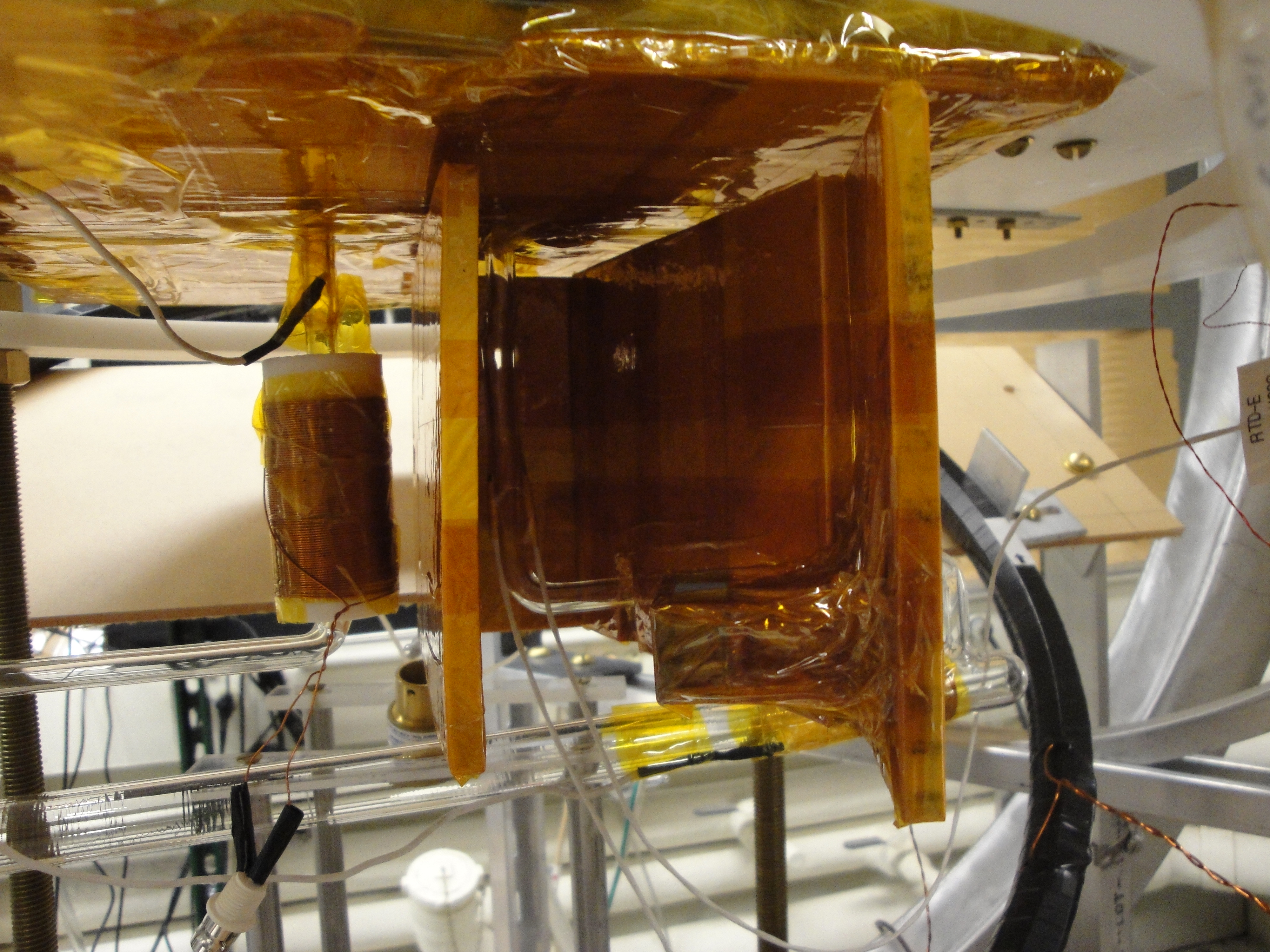
| 12:58, 2 November 2011 | Protovec-1 mounting8.jpg (file) |  |
4.03 MB | Protovec-1 installed in UVa SEOP Oven. | 1 |
| 12:57, 2 November 2011 | Protovec-1 mounting7.jpg (file) |  |
4.84 MB | Protovec-1 prepared to go into UVa SEOP Oven. | 1 |
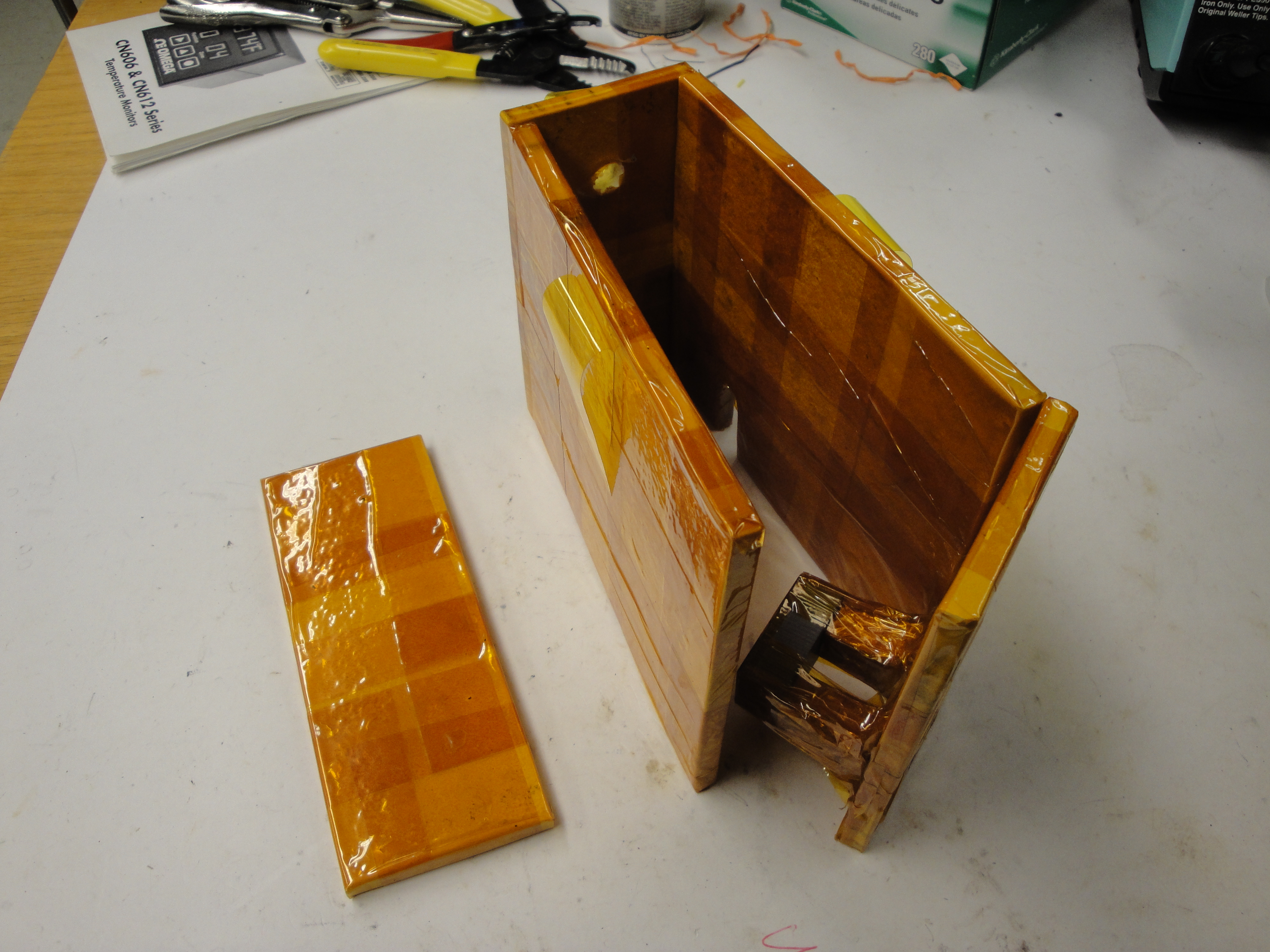
| 12:56, 2 November 2011 | Protovec-1 mounting6.jpg (file) |  |
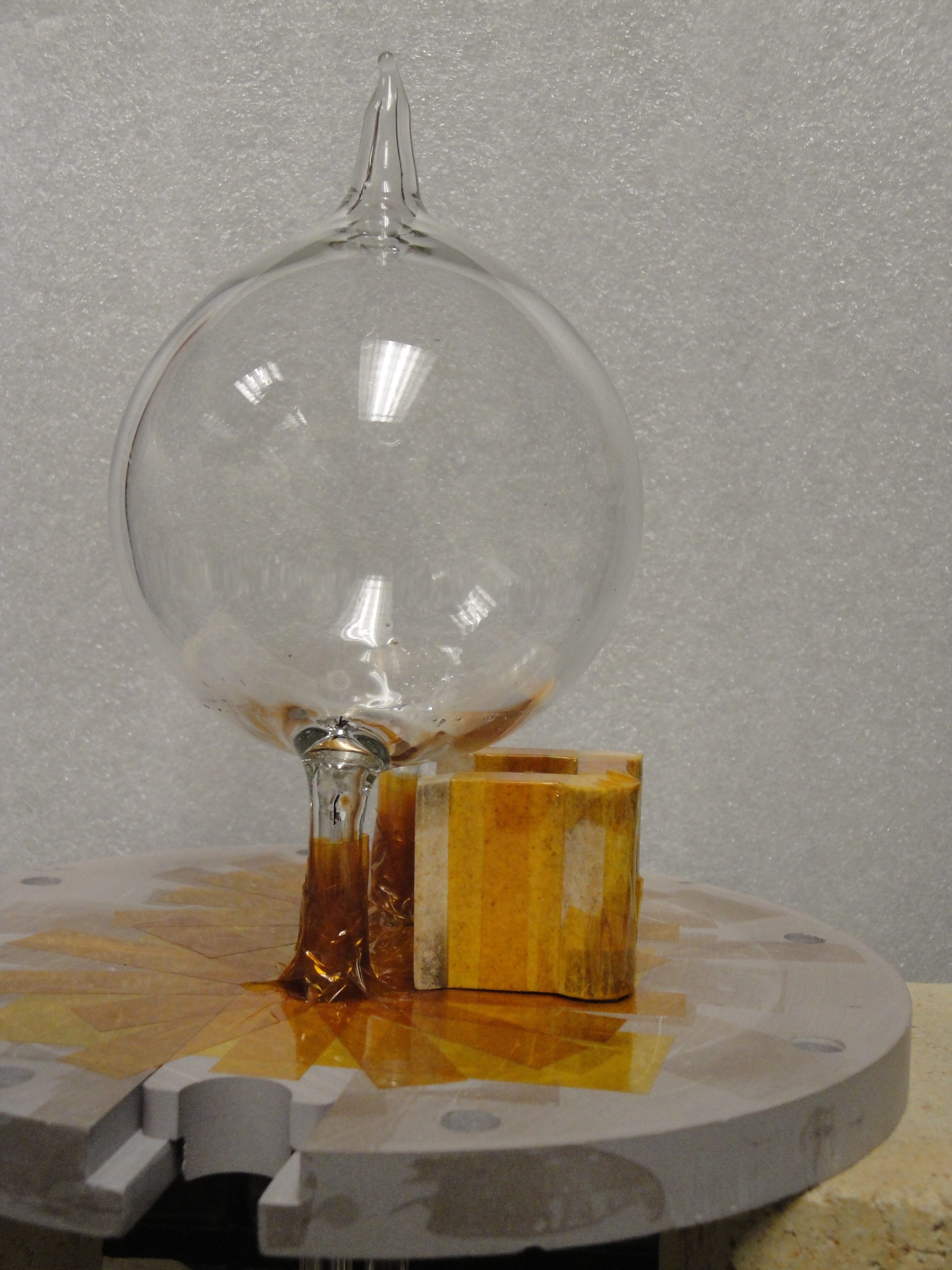
4.2 MB | Cell securely mounted on oven cell holder plate. | 1 |
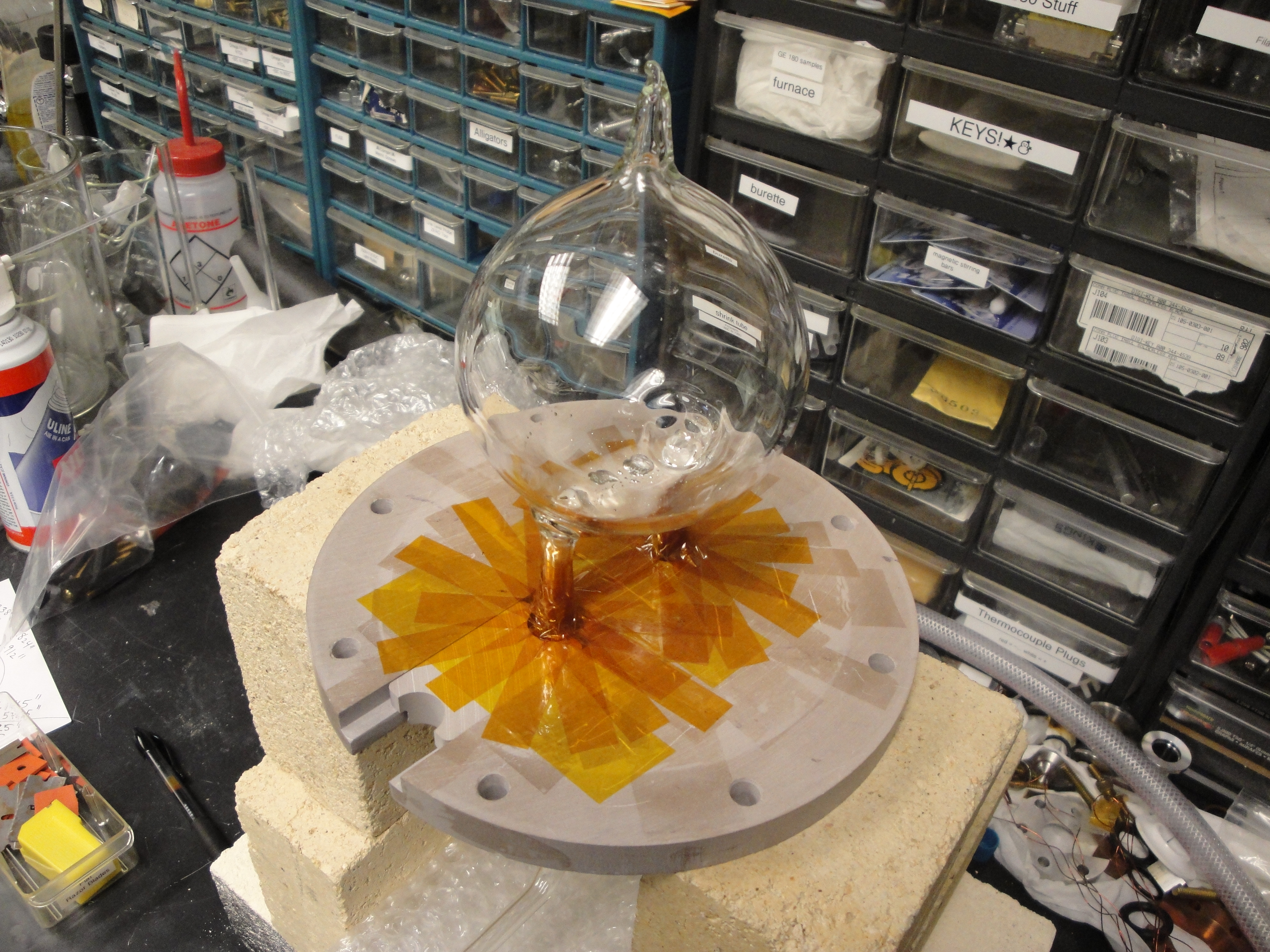
| 12:54, 2 November 2011 | Protovec-1 mounting5.jpg (file) |  |
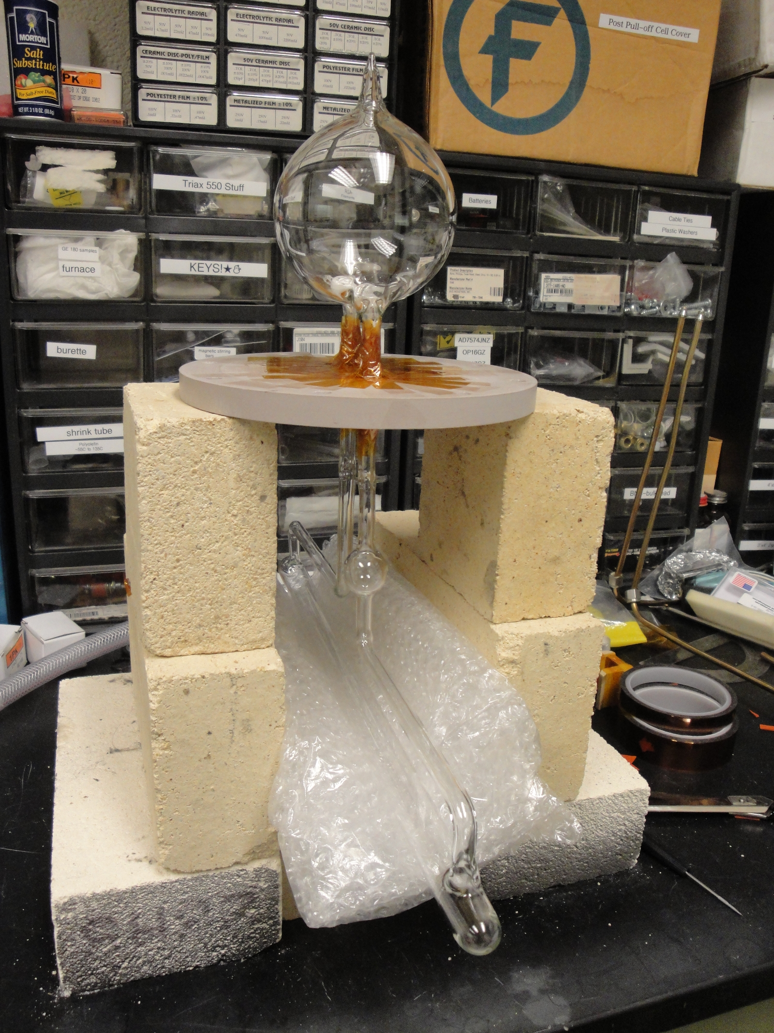
4.09 MB | Cell mounted on plate with Kapton tape on both top and bottom surfaces. | 1 |
| 12:53, 2 November 2011 | Protovec-1 mounting4.jpg (file) |  |
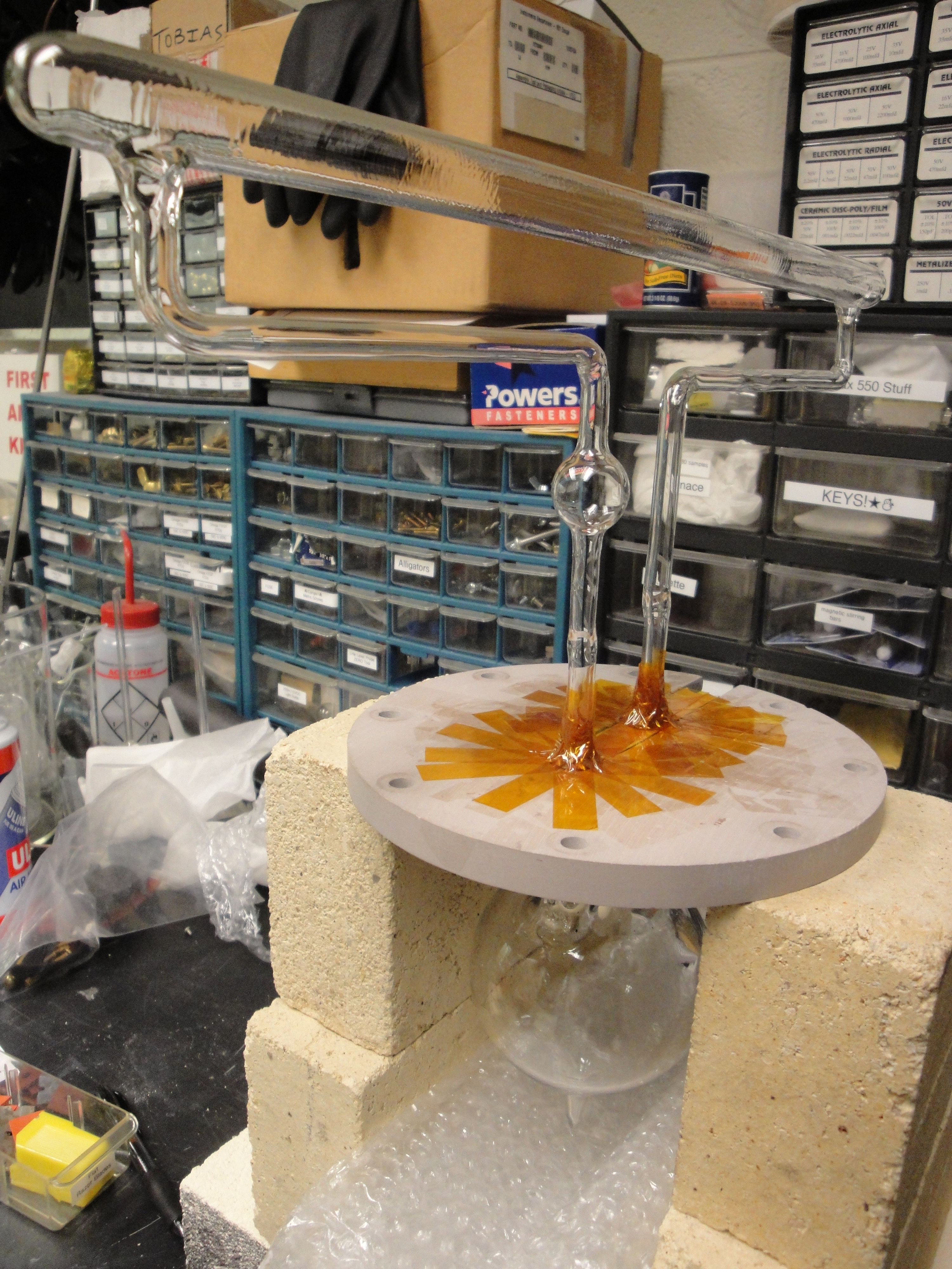
4.71 MB | Closeup of Kapton tape on underside of cell mounting plate. | 1 |
| 12:24, 2 November 2011 | Protovec-1 mounting3.jpg (file) |  |
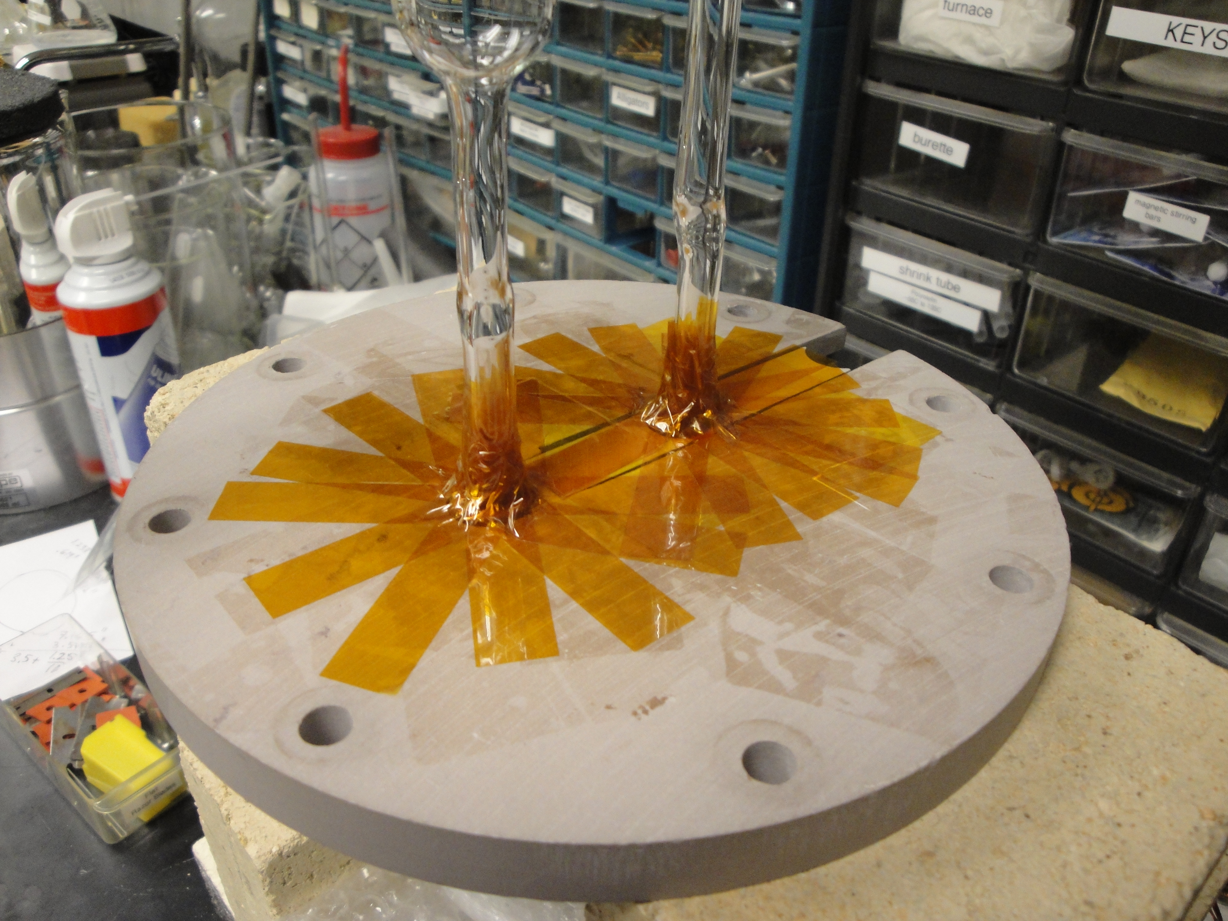
4.02 MB | Kapton taping the underside of cell mounting plate. | 1 |
| 12:22, 2 November 2011 | Protovec-1 mounting2.jpg (file) |  |
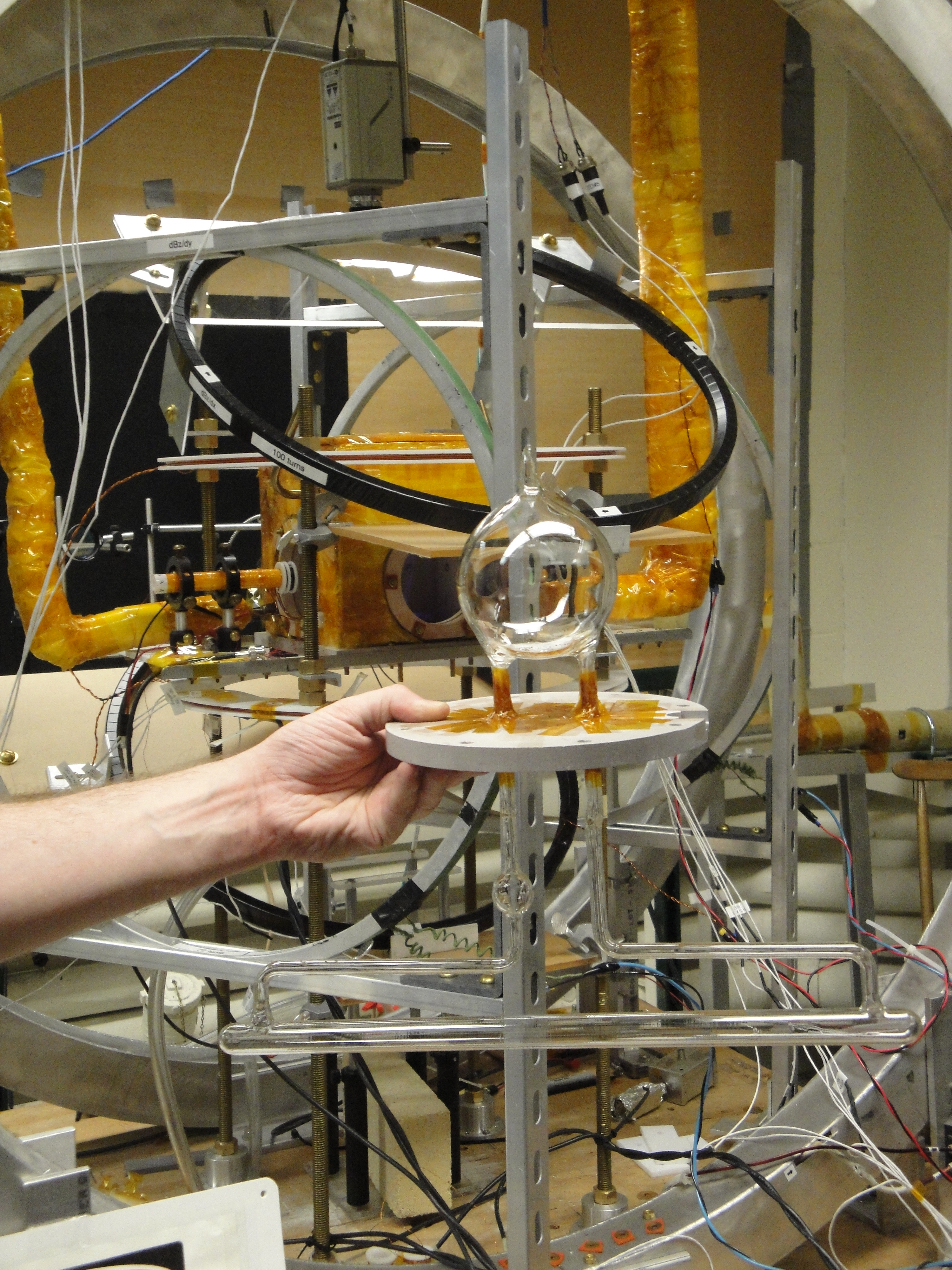
4.01 MB | Spacer used to set proper height of cell so that a 3.5" pumping chamber will be centered on oven windows. | 1 |
| 12:20, 2 November 2011 | Protovec-1 mounting1.jpg (file) |  |
4.76 MB | Mounting cell with Kapton tape onto an Alumina Silicate Ceramic oven plate. | 1 |
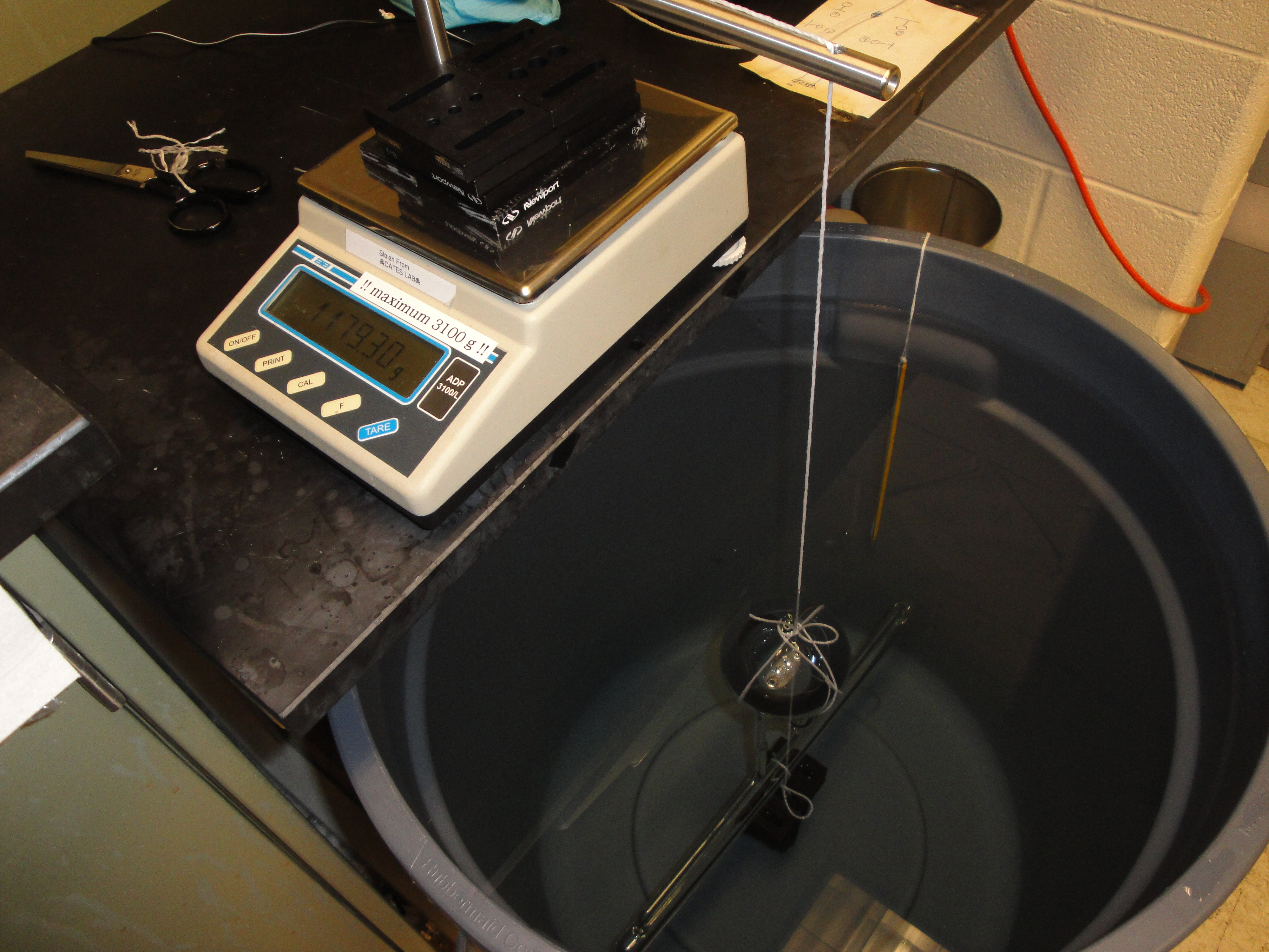
| 22:53, 1 November 2011 | Protovec-1 buoyancy4.jpg (file) |  |
4.63 MB | The buoyancy "mass of cell + block" measurement for Protovec-1. | 1 |
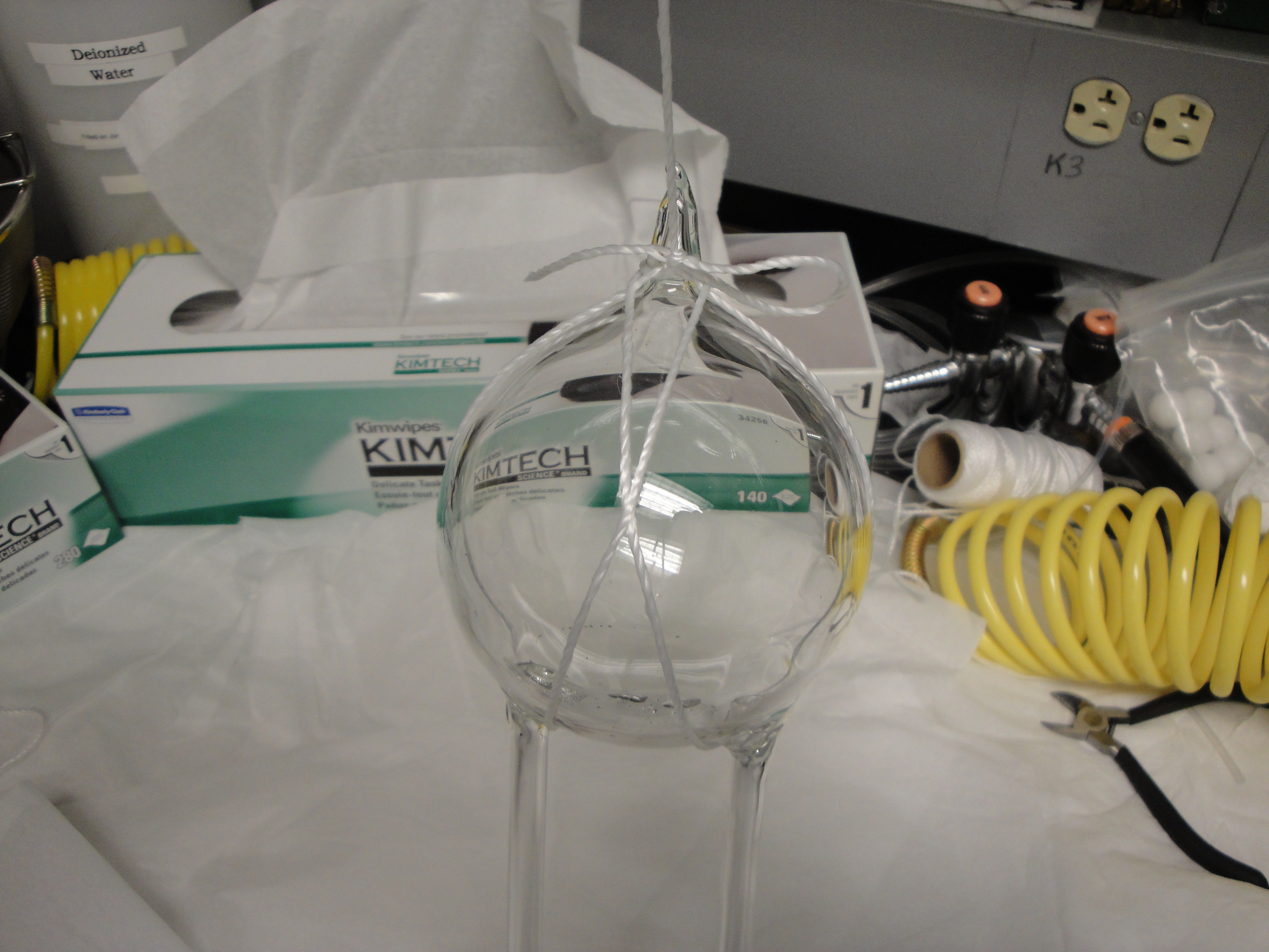
| 22:51, 1 November 2011 | Protovec-1 buoyancy3.jpg (file) |  |
4.38 MB | View of block tied to Protovec-1 target chamber for buoyancy measurement. | 1 |
| 22:50, 1 November 2011 | Protovec-1 buoyancy2.jpg (file) |  |
4.48 MB | Pumping Chamber view of Protovec-1 tied up for buoyancy measurement. | 1 |
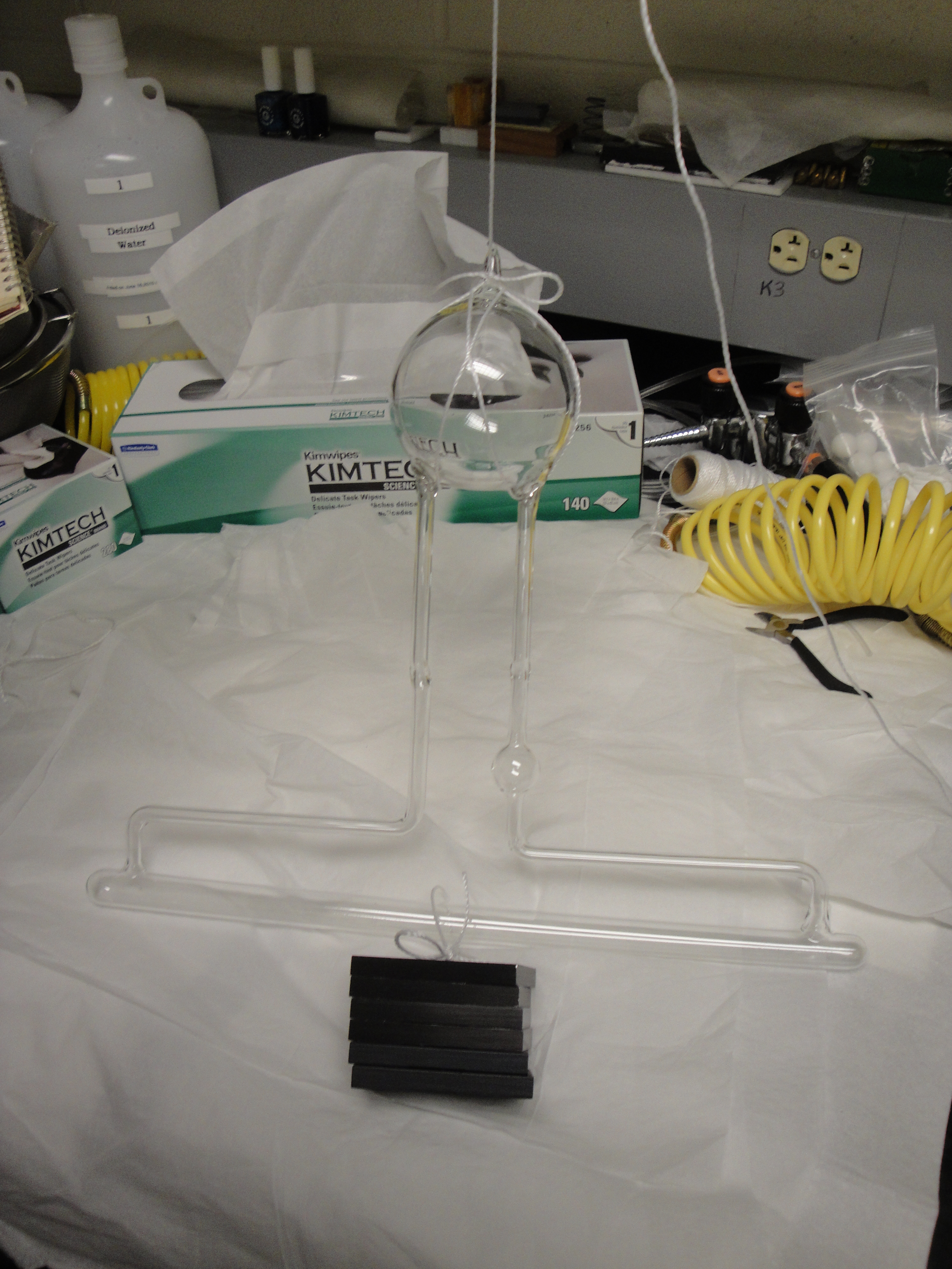
| 22:48, 1 November 2011 | Protovec-1 buoyancy1.jpg (file) |  |
4.01 MB | Protovec-1 tied up with a block for the Cell + Block mass determination of the buoyancy measurement. | 1 |
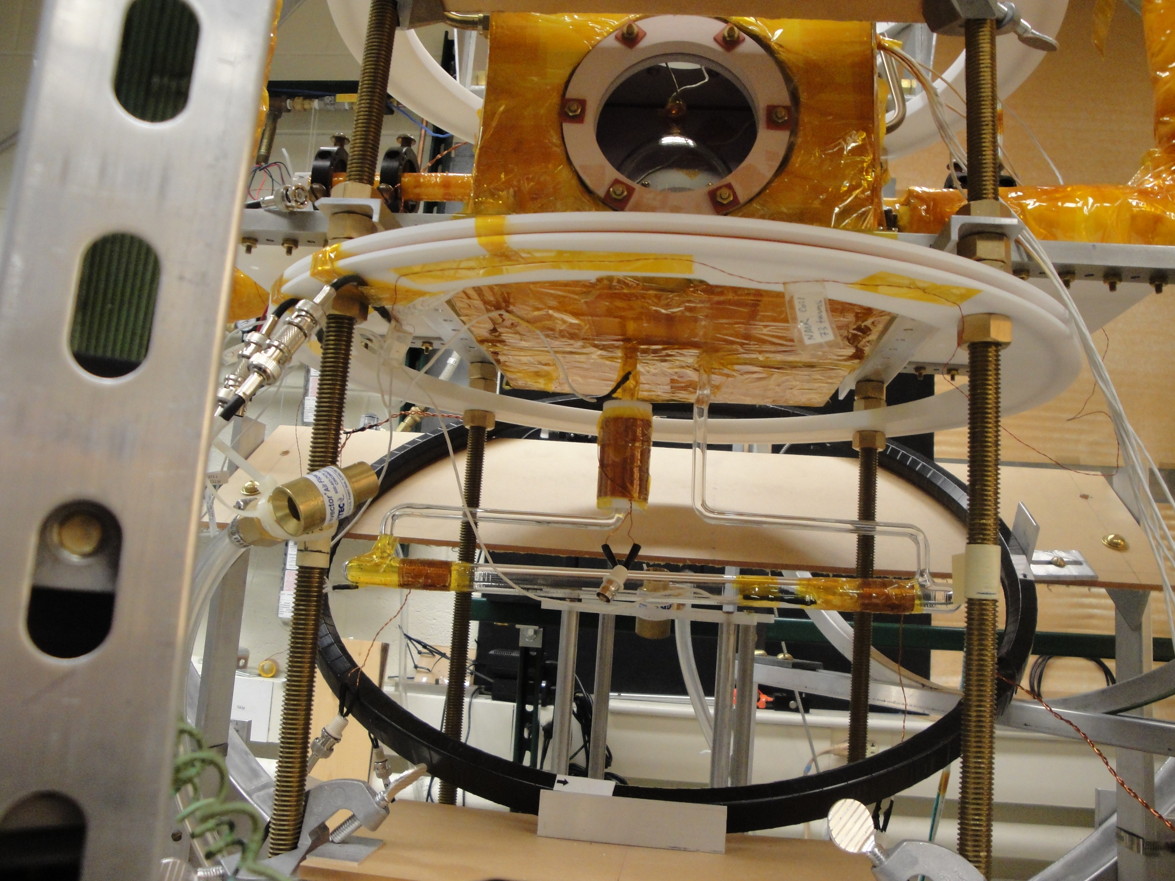
| 21:18, 1 November 2011 | Protovec-1 coils4.jpg (file) |  |
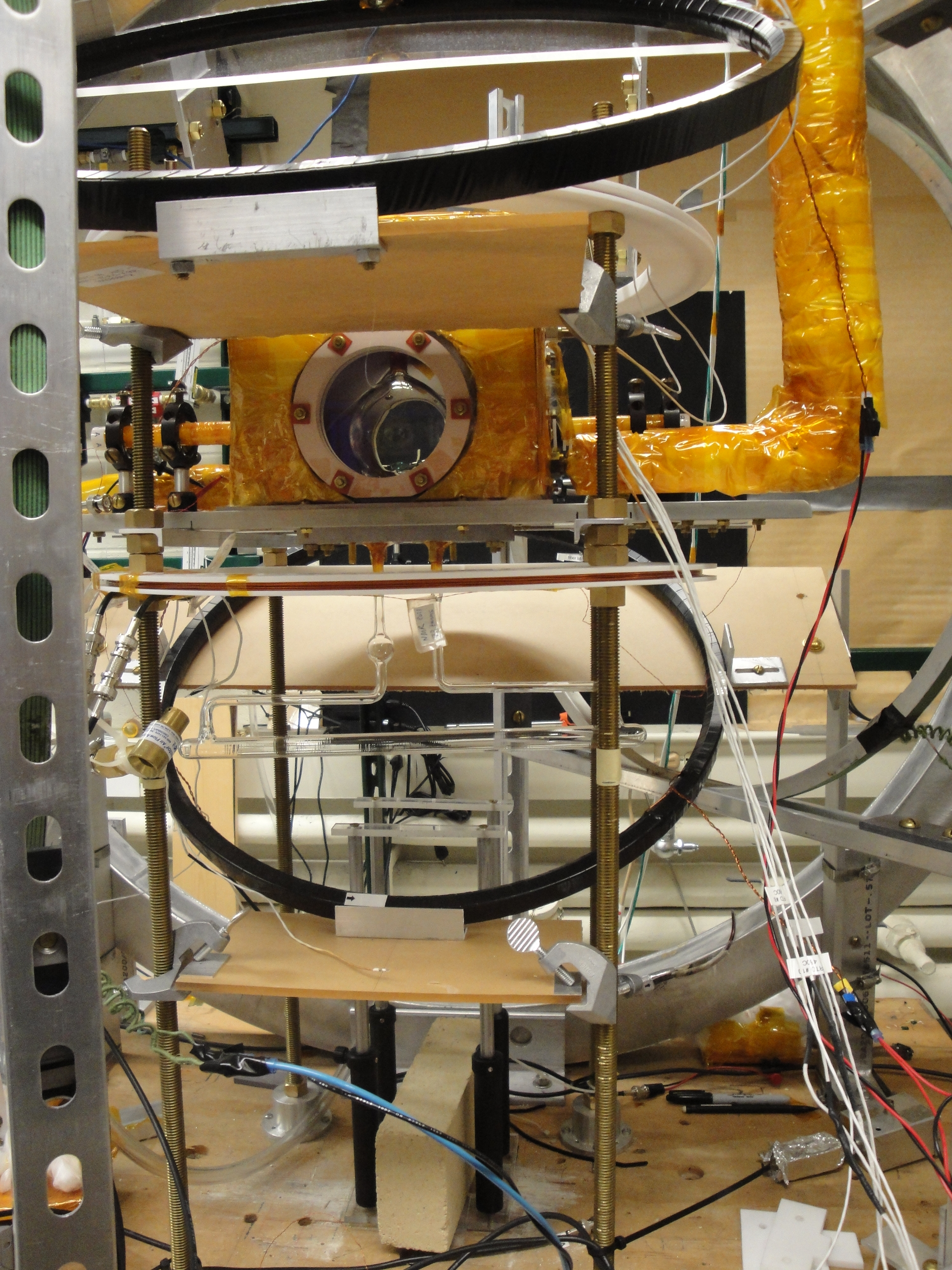
4.69 MB | View of pNMR on ''left'' and two RTDs for Convection Drive Oven on the ''right''. | 1 |
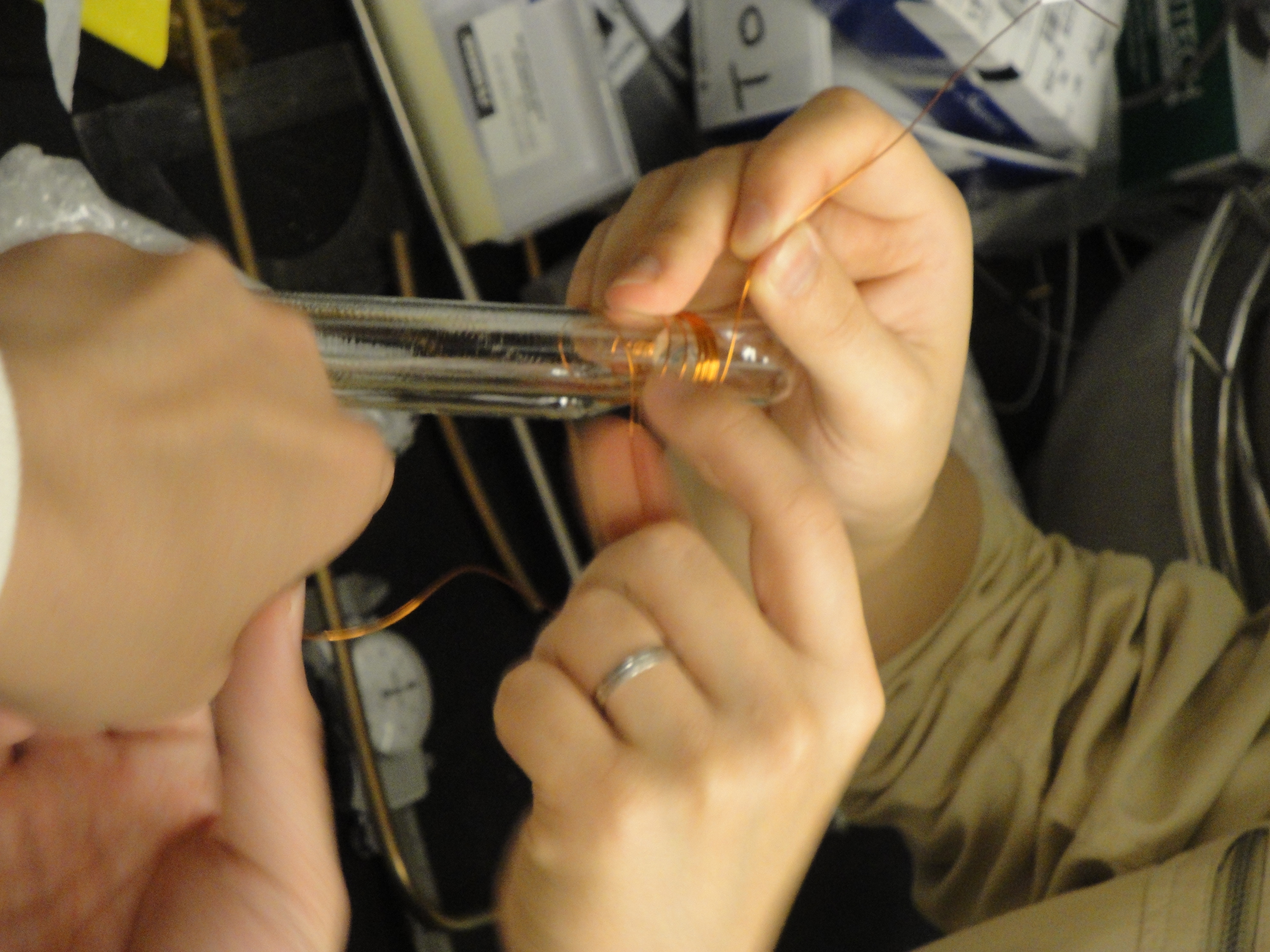
| 21:15, 1 November 2011 | Protovec-1 coils2.jpg (file) |  |
4.73 MB | Wrapping 80-turn pNMR solenoid pickup coil on Protovec-1. | 1 |
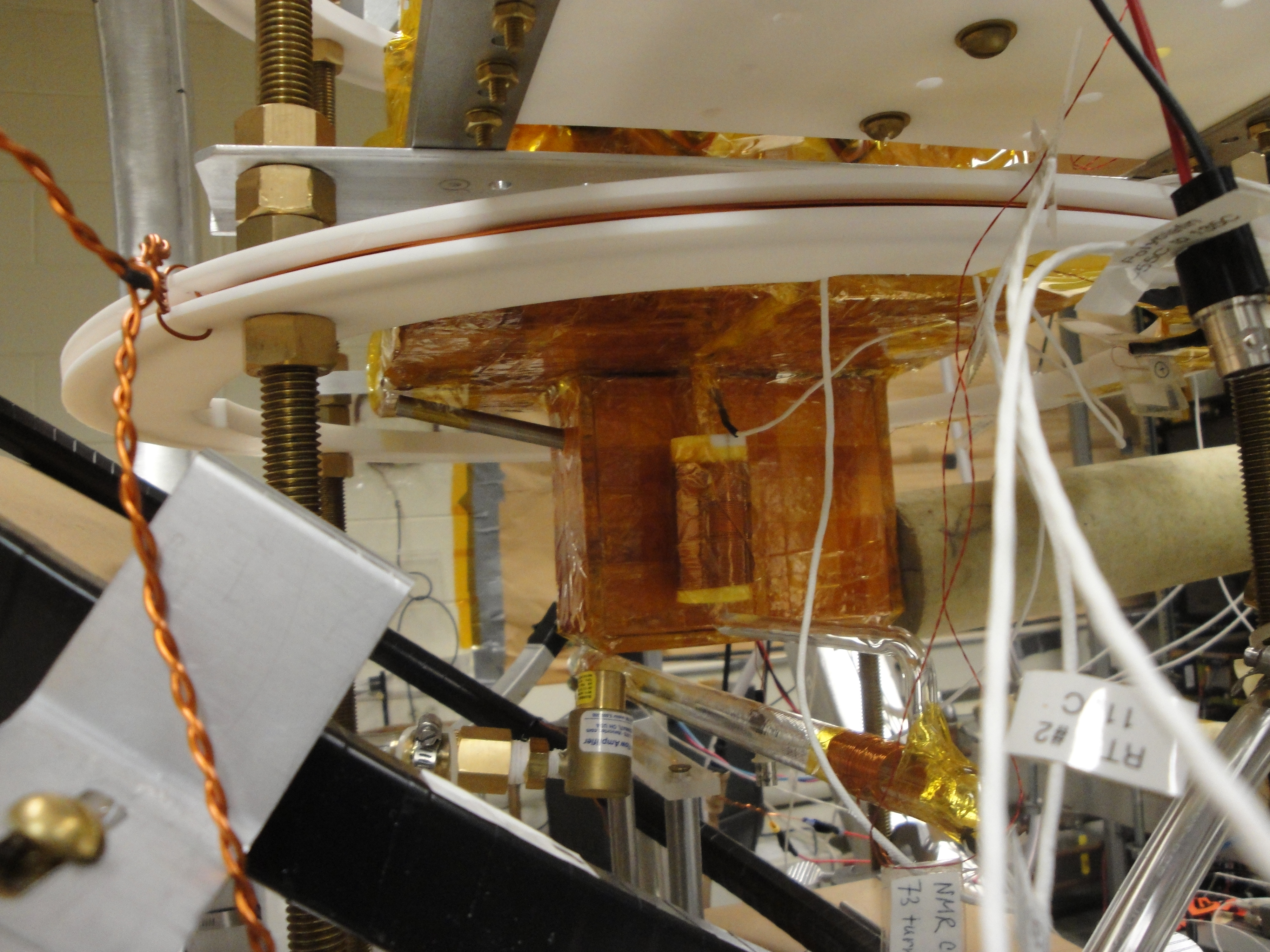
| 21:08, 1 November 2011 | Protovec-1 coils3.jpg (file) |  |
4.61 MB | View of three pickup coils: a pNMR coil and two TC coils. | 1 |
| 20:59, 1 November 2011 | Protovec-1 coils1.jpg (file) |  |
4.56 MB | Wrapping 50-turn solenoid pickup coil around Protovec-1 target chamber. | 2 |
| 20:46, 1 November 2011 | Protovec-1 drive oven3.jpg (file) |  |
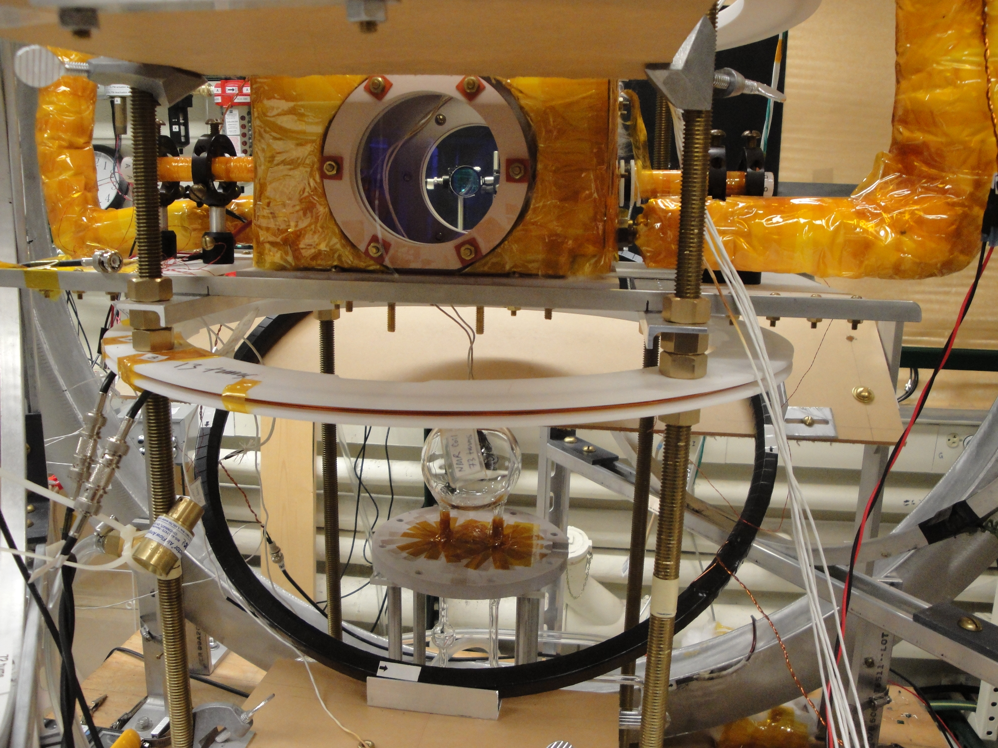
4.73 MB | Side view of Drive Oven with pNMR coil in front of it. | 1 |
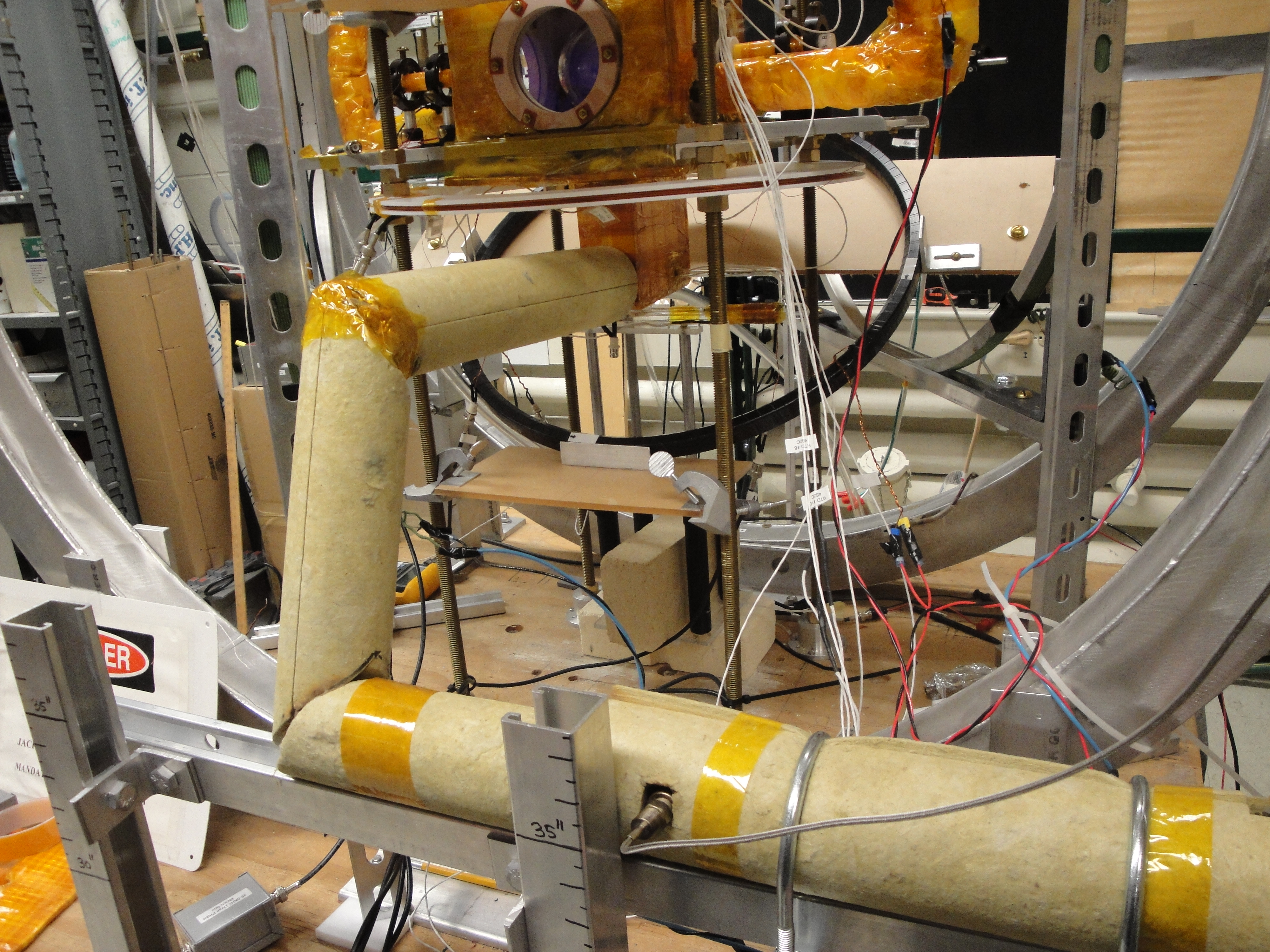
| 20:43, 1 November 2011 | Protovec-1 drive oven2.jpg (file) |  |
4.84 MB | Full Drive Oven system installed, with PureFlow heater (wrapped in insulation) and thermocouple with wire in the foreground. | 1 |
| 20:40, 1 November 2011 | Protovec-1 drive oven1.jpg (file) |  |
4.7 MB | View of Drive Oven partially installed & open to allow one to see hot air input blocking bar. | 2 |
| 20:35, 1 November 2011 | Protovec-1 drive oven0.jpg (file) |  |
4.36 MB | Convection Drive oven as used with Protovec-1 in transverse mode Nov. 2011 | 2 |
| 19:19, 1 November 2011 | Bran in box.jpg (file) |  |
4.74 MB | First prototype convection cell tested at UVa in 2008/2009. | 1 |
| 17:05, 1 November 2011 | Protovec-1 cryo.jpg (file) |  |
1.77 MB | Protovec-1 immersed in LHe-4 during gas filling procedure. | 3 |
| 17:02, 1 November 2011 | Protovec-1 gas-system.jpg (file) |  |
1.96 MB | Protovec-1 attached to glass manifold on the UVa gas system | 1 |
| 16:56, 1 November 2011 | Protovec1 dimensions 20oct2011.pdf (file) | 8 KB | Actual dimensions of the prototype cell Protovec-1 | 2 | |
| 16:16, 1 November 2011 | Next Convection Cell 16may2011.pdf (file) | 132 KB | Final drawing given to Mike Souza to fabricate the prototype cell Protovec-1. | 1 |