


Next: Operating Procedure
Up: Møller Polarimeter
Previous: Spectrometer Description
Contents
The Møller polarimeter detector is located in the shielding box downstream
of the dipole and consists of two identical modules placed symmetrically about a vertical
plane containing the beam axis, thus enabling
coincidence measurements.
Each part of the detector includes:
The HV crate is located in the Hall A rack 15. The crate name is hac42.
HV for the lead glass detectors is tuned in order to align the Møller peak
position at a ADC channel 300 for each module, which means that the gain
of the the bottom modules is about 50% higher than the gain of the top
modules.
The values of HV are presented in table 2.9.
In order to obtain the HV values for an arbitrary energy:
- -
- login to adaqs3 as moller;
- -
-
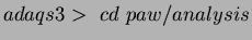 , start PAW, select Workstation type 3;
- -
-
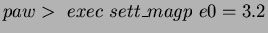 , the required values of
  or
or  are printed.
Next: Operating Procedure
Up: Møller Polarimeter
Previous: Spectrometer Description
Contents
Joe Mitchell
2000-02-29