 |
 |
 |
 |
| Home Page | Beam Energy Measurements |
EP Method | Hall A Homepage |
 |
 |
 |
 |
| Home Page | Beam Energy Measurements |
EP Method | Hall A Homepage |
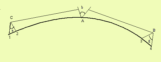
When beam enters Hall A, it passes through a forty-meter arc section that is between the accelerator and the Hall A end station. This arc contains eight dipole magnets (and nine quadrupole magnets), which bends and directs the beam. The purpose of the Arc-Energy method is to measure the energy of the beam as it reaches Hall A having passed through the arc. The method was developed by the Frech collaboration of Pascal Vernin and the Saclay group, and measures the energy, E, as a function of the field integral of the eight-dipole magnets and the bend angle of the arc. This is expressed by the following:
    /
    E=c( |B.dl )/q
  /
The bend angle of the beam is measured by using four wire scanners, two (1 and 2) at the upstream entrance of the arc (C) and two (3 and 4) at the downstream exit of the arc (B). Each pair of scanners is about 4 meters apart, and each scan the beam giving a horizontal profile of the beam. They do this by moving horizontally a vertical wire across the beam detecting radiation from the beam using a photomultiplier tube. They move forward and backward across the beam, and the profiles from each scanner are compared with the other in the respective pair to come up with a horizontal beam angle both upstream and downstream, a andg respectively. To complete the angle measurement, auto collimation techniques are implemented. A pair of mirrors is placed over the middle point of the arc tunnel ("A"), one mirror facing a marker at the axis of scanners 1 and 2 while the other mirror faces a marker at hte axis of scanners 3 and 4. The mirrors can be made so that the angle, b, between them will remain constant forever. The sum of all the angles can then taken to find the the total bend angle, q (a+g+b=q).
 |
The eight dipoles are located in a vacuum and are therefore inaccessable for a field integral measurement. Instead a ninth reference magnet is used, which is both identical and powered in series with the others. It is located in a separate building and is equipped with a device that measures its field integral with an accuracy of one part in 10-5. The "translating coil" technique is implemented here, measuring the flux changes of the two small coils as they pass horizontally along the beam path at a constant velocity through the magnet. The coils are separated by what must be an accurately determined length, L. The coils simultaneously pass through the entrance and exit ends, experiencing positive voltage at the entrance, no voltage in the middle region, and vegative valtage at the exit. As the coils pass, their respective signals are cancelled resulting in a null measurement. A second integration of the voltage yields the necessary vertical component of the field. This results in the following formula:
                               /                //
         |B.dl= B0.L+(s/a)||V.dt2
   /                //
Other Links