The measurements of the dead time of the discriminator module type of TD8000 and the PLU module type of LeCroy-2365 have been performed on April 30, 2010. The pulse generator type of HP8013B and the oscilloscope were used for these measurements. Two pulses are formed by special circuit with settable time interval in the range of 2ns-30ns between the first and the second pulse. These pulses are fed to the input of the discriminator module. The output of the discriminator was connected to the one channel of the oscilloscope to view the signals.
The next steps were performed to measure of dead time : the decrease the time interval between two pulses until on the output of discriminator is generated only one pulse. This time is corresponds to the dead-time of the discriminator.
The first measurements was performed with signals from the output of the PMT that was produced by LED generator.
The second measurements was performed with signals from the pulse generator.
There are results of these measurements:
    Input pulse amplitude, mV   -500
    Input pulse width, ns        20(LED), 7-15(pulse generator)
    Input pulse rate, kHz        4.5(LED), 10(pulse generator)
    Discriminator threshold, mV  400(LED), 100-400(pulse generator)

    channel     dead-time(ns)
    4           22 (LED), 20(pulse generator)
    5           20 (LED), 18(pulse generator)
So, the dead-time of the discrimintor TD8000 is ~22ns.
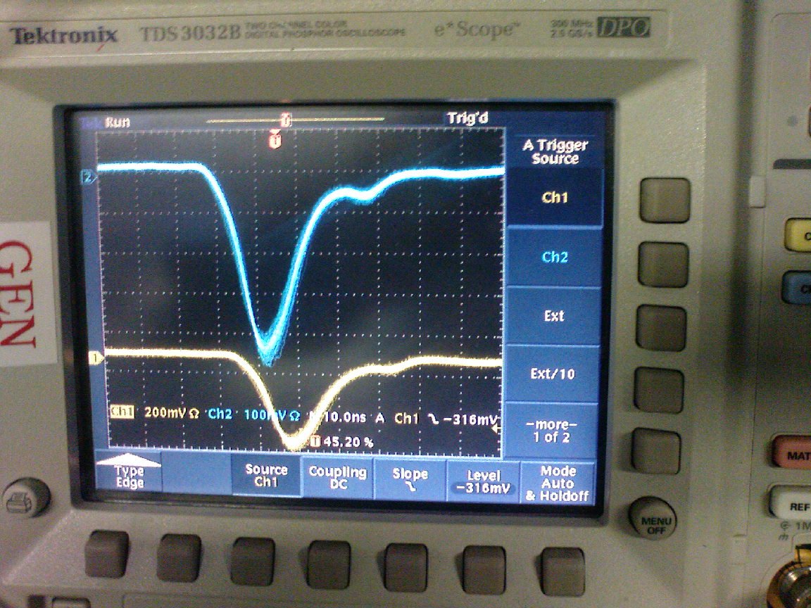
This picture shows signals from the PMT that have been produced by LED generator.
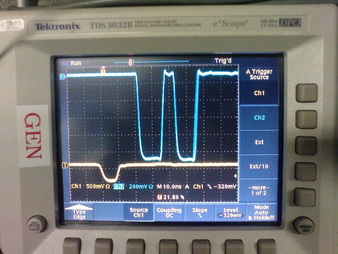
This picture shows signals(blue color) on the input of the discriminator from the pulse generator.
This picture shows signals(blue color) on the output of the discriminator.
The measurement of the PLU module was performed with the same method but only signals from pulse generator were used.
The signals are fed to the input #1 and input #2 of the PLU. The oscilloscope was connected to the output #8 of the PLU.
The output #8 of the PLU module was configured for coincidence of inputs #1 and #2.
The parameters of signal for these measurements are:
    Input pulse width, ns        7-15 (pulse generator)
    Input pulse rate, kHz        10 (pulse generator)
    Pulse delay, ns              8-25
For input pulses with width of 7ns and delay between pulses in 8ns the PLU module is still generate two pulses on its output. There does not seen any dead-time of the PLU module for these parameters of the input signals.
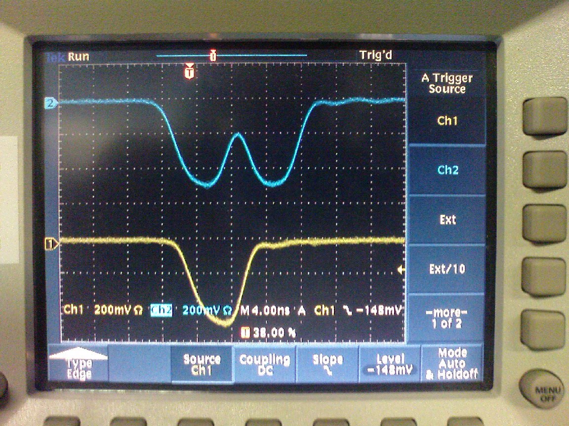
This picture shows signals(blue color) on the input of the PLU module from the pulse generator.
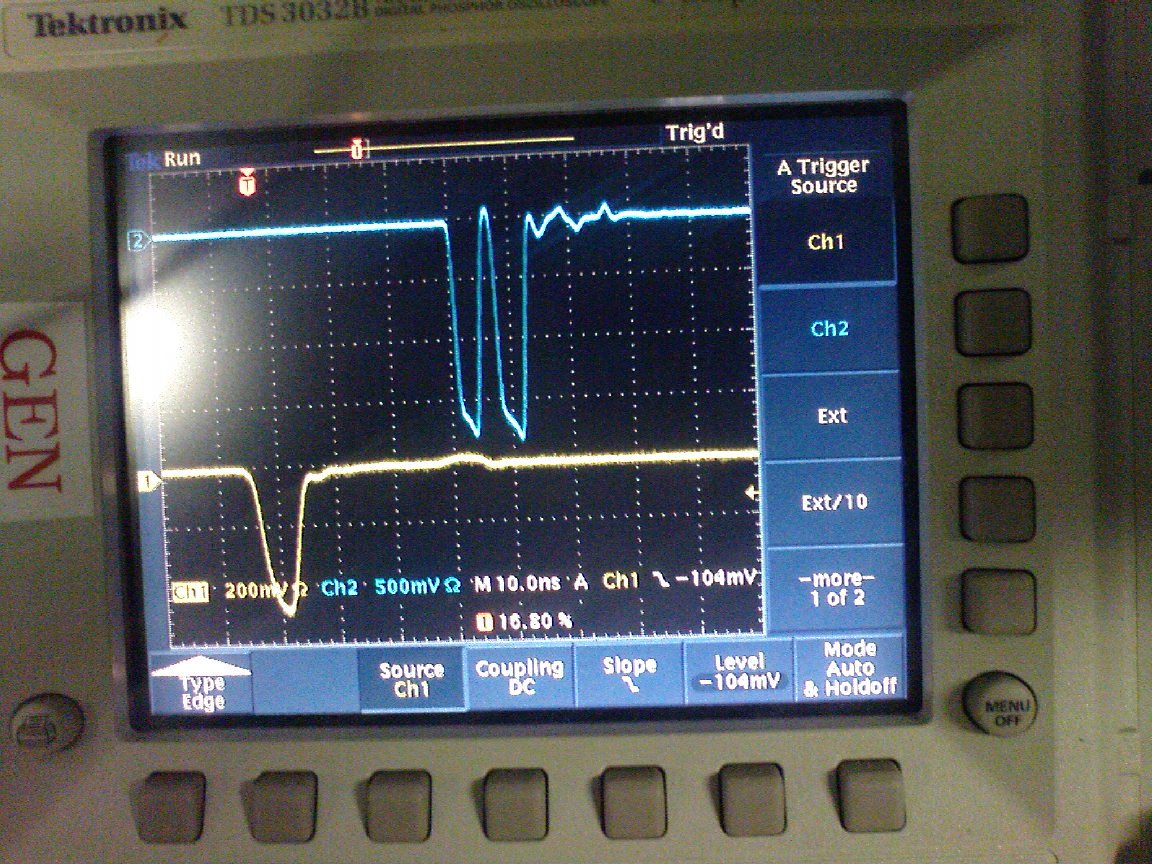
This picture shows signals(blue color) on the output of the PLU module.
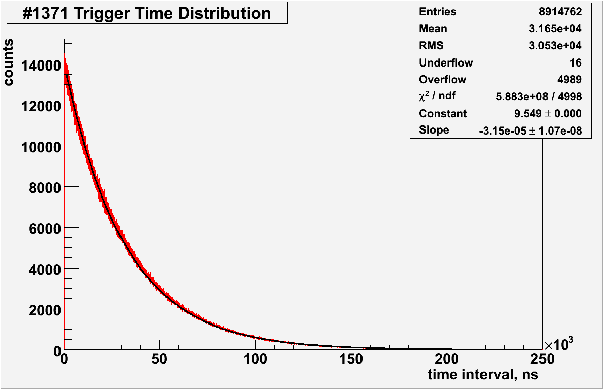
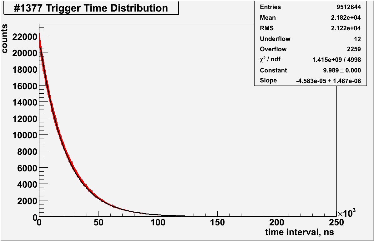
There is a free running timer (48bit, 250MHz) on-board of the FADC. The time stamp of the every event (trigger) is recorded within of event data block.
The plots of the time intervals distribution of FADC events for run #1371 presented on
pic.1 ( "ps")
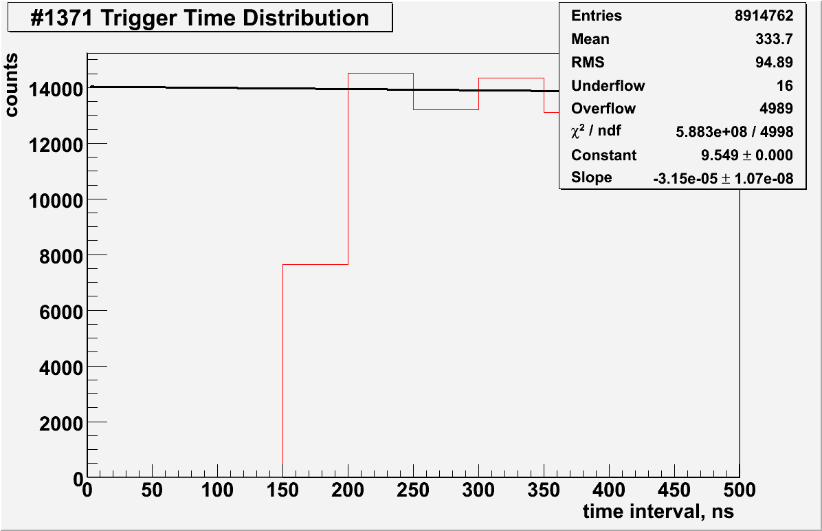
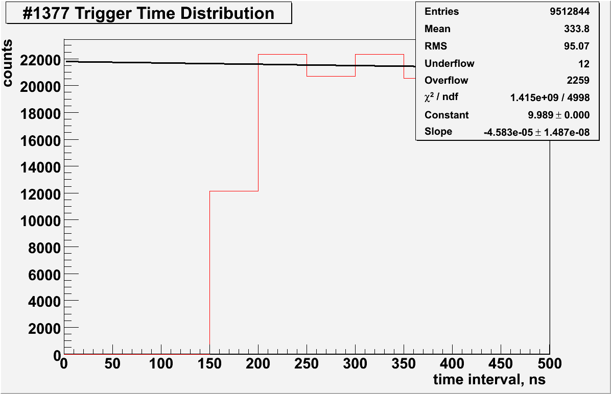
and pic.2(scaled) ( "ps").
The red line represent data, the black line is fitting with exponential function.
There is some shift about 150ns from zero time(pic.2(scaled)), that corresponds probably to the dead-time of the FADC.
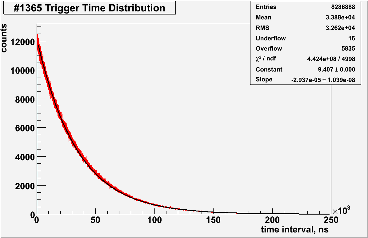
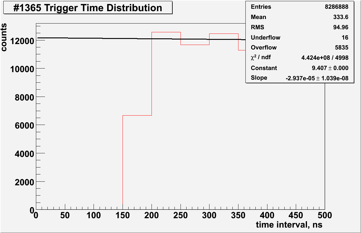
The trigger time distribution has been extracted for few runs with the same settings of FADC :
Parameters of FADC for the run 1371 (plot):
    Target #2 (4u)
    Beam current  3.0 uA
    Helicity      30Hz

    FA_SUM_THRESH_CR   8500
    FA_SUM_THRESH_CL   8500

    FA_CHN_THRESH_SR     500
    FA_CHN_THRESH_SL     500
    FA_CHN_THRESH_CR     400
    FA_CHN_THRESH_CL     400

    FADC_PRESCALE_CL   40
    FADC_PRESCALE_CR   40
    FADC_PRESCALE_CRL  1