Difference between revisions of "Trigger"
(→Open Issues) |
(→Trigger patterns) |
||
| (85 intermediate revisions by 5 users not shown) | |||
| Line 1: | Line 1: | ||
Back to [[DVCS3]] | Back to [[DVCS3]] | ||
| + | === Deadtime script === | ||
| + | Analyze deadtime on any aonl machines: "godvcs", "cd marco/deadtime/", "analyzer", ".L deadtime.C", "deadtime(run_number)". | ||
| + | === DAQ Trigger configuration === | ||
| − | + | That file is kept under dvcs@intelhadvcs1:~/config_files | |
| + | |||
| + | <PRE> | ||
| + | ## Example configuration file | ||
| + | # | ||
| + | Global Threshold = 750 | ||
| + | Cluster Threshold = 250 | ||
| + | Require Cluster = 0 | ||
| + | # Gate width setting is in increments of 5ns | ||
| + | Gate Width = 14 | ||
| + | ##### | ||
| + | # Prescale settings are in powers of two: | ||
| + | # ___Behavior__________ Setting | ||
| + | # PRESCALE_VAL_DISABLED 0 | ||
| + | # PRESCALE_VAL_NONE 1 | ||
| + | # PRESCALE_VAL_2 2 | ||
| + | # PRESCALE_VAL_4 3 | ||
| + | # PRESCALE_VAL_8 4 | ||
| + | # PRESCALE_VAL_16 5 | ||
| + | # PRESCALE_VAL_32 6 | ||
| + | # PRESCALE_VAL_64 7 | ||
| + | # PRESCALE_VAL_128 8 | ||
| + | # PRESCALE_VAL_256 9 | ||
| + | # PRESCALE_VAL_512 10 | ||
| + | # PRESCALE_VAL_1024 11 | ||
| + | # PRESCALE_VAL_2048 12 | ||
| + | # PRESCALE_VAL_4096 13 | ||
| + | # PRESCALE_VAL_8192 14 | ||
| + | # PRESCALE_VAL_16384 15 | ||
| + | # Prescale channel assignments are: | ||
| + | # PRESCALE_ID_CLOCK 0 | ||
| + | # PRESCALE_ID_COSMIC 1 | ||
| + | # PRESCALE_ID_S2M_NCER 2 | ||
| + | # PRESCALE_ID_S0_S1 3 | ||
| + | # PRESCALE_ID_S0_S2M 4 | ||
| + | # PRESCALE_ID_S0_CER 5 | ||
| + | # PRESCALE_ID_S1_S2M 6 | ||
| + | # PRESCALE_ID_S1_CER 7 | ||
| + | # PRESCALE_ID_S2M_CER 8 | ||
| + | ##### | ||
| + | Prescale_0 Clock = 0 | ||
| + | Prescale_1 Cosmic = 0 | ||
| + | Prescale_2 S2M and NCER = 1 | ||
| + | Prescale_3 S0 and S1 = 0 | ||
| + | Prescale_4 S0 and S2M = 0 | ||
| + | Prescale_5 S0 and CER = 0 | ||
| + | Prescale_6 S1 and S2M = 0 | ||
| + | Prescale_7 S1 and CER = 0 | ||
| + | Prescale_8 S2M and CER = 1 | ||
| + | ##### | ||
| + | ## The following lines can be used to enable autovalidation; | ||
| + | ## uncomment any that are desired. | ||
| + | ##### | ||
| + | # Autovalidate S2M_NCER_SCALED | ||
| + | # Autovalidate S2M_CER2_SCALED | ||
| + | # Autovalidate S2M_CER_SCALED | ||
| + | # Autovalidate S1_CER_SCALED | ||
| + | # Autovalidate S1_S2M_SCALED | ||
| + | # Autovalidate S0_CER_SCALED | ||
| + | # Autovalidate S0_S2M_SCALED | ||
| + | # Autovalidate S0_S1_SCALED | ||
| + | # Autovalidate TRIG_VME | ||
| + | # Autovalidate COSMIC_SCALED | ||
| + | # Autovalidate TRIGCLK_SCALED | ||
| + | ## | ||
| + | |||
| + | BEGIN_PEDESTALS | ||
| + | # Data1 Pedestals: | ||
| + | 2048 2048 2048 2048 2048 2048 2048 2048 # Hardware channels 001-008 | ||
| + | 2048 2048 2048 2048 2048 2048 2048 2048 # Hardware channels 009-016 | ||
| + | 2048 2048 2048 2048 2048 2048 2048 2048 # Hardware channels 017-024 | ||
| + | 2048 2048 2048 2048 2048 2048 2048 2048 # Hardware channels 025-032 | ||
| + | 2048 2048 2048 2048 2048 2048 2048 2048 # Hardware channels 033-040 | ||
| + | 2048 2048 2048 2048 2048 2048 2048 2048 # Hardware channels 041-048 | ||
| + | 2048 2048 2048 2048 2048 2048 2048 2048 # Hardware channels 049-056 | ||
| + | 2048 2048 2048 2048 2048 2048 2048 2048 # Hardware channels 057-064 | ||
| + | 2048 2048 2048 2048 2048 2048 2048 2048 # Hardware channels 065-072 | ||
| + | 2048 2048 2048 2048 2048 2048 2048 2048 # Hardware channels 073-080 | ||
| + | |||
| + | # Data2 Pedestals: | ||
| + | 2048 2048 2048 2048 2048 2048 2048 2048 # Hardware channels 081-088 | ||
| + | 2048 2048 2048 2048 2048 2048 2048 2048 # Hardware channels 089-096 | ||
| + | 2048 2048 2048 2048 2048 2048 2048 2048 # Hardware channels 097-104 | ||
| + | 2048 2048 2048 2048 2048 2048 2048 2048 # Hardware channels 105-112 | ||
| + | 2048 2048 2048 2048 2048 2048 2048 2048 # Hardware channels 113-120 | ||
| + | 2048 2048 2048 2048 2048 2048 2048 2048 # Hardware channels 121-128 | ||
| + | 2048 2048 2048 2048 2048 2048 2048 2048 # Hardware channels 129-136 | ||
| + | 2048 2048 2048 2048 2048 2048 2048 2048 # Hardware channels 137-144 | ||
| + | |||
| + | # Data3 Pedestals: | ||
| + | 2048 2048 2048 2048 2048 2048 2048 2048 # Hardware channels 145-152 | ||
| + | 2048 2048 2048 2048 2048 2048 2048 2048 # Hardware channels 153-160 | ||
| + | 2048 2048 2048 2048 2048 2048 2048 2048 # Hardware channels 161-168 | ||
| + | 2048 2048 2048 2048 2048 2048 2048 2048 # Hardware channels 169-176 | ||
| + | 2048 2048 2048 2048 2048 2048 2048 2048 # Hardware channels 177-184 | ||
| + | 2048 2048 2048 2048 2048 2048 2048 2048 # Hardware channels 185-192 | ||
| + | 2048 2048 2048 2048 2048 2048 2048 2048 # Hardware channels 193-200 | ||
| + | 2048 2048 2048 2048 2048 2048 2048 2048 # Hardware channels 201-208 | ||
| + | |||
| + | END_PEDESTALS | ||
| + | </PRE> | ||
| + | |||
| + | === Trigger patterns === | ||
| + | |||
| + | Trigger patterns: | ||
| + | The lowest six bits of the triggerPattern word (mask value=0x3f) record the status of the raw trigger inputs. | ||
| + | Depending on the prescale settings, a trigger input may be present even if it was not included in the event | ||
| + | trigger for that event. | ||
| + | {| border="1" cellpadding="3" | ||
| + | | Trigger input | ||
| + | | Bit pattern | ||
| + | | Value | ||
| + | |- | ||
| + | | COSMIC || 0x00001 || 1 | ||
| + | |- | ||
| + | | TRIGCLK || 0x00002 || 2 | ||
| + | |- | ||
| + | | SO || 0x00004 || 4 | ||
| + | |- | ||
| + | | S1 || 0x00008 || 8 | ||
| + | |- | ||
| + | | S2M || 0x00010 || 16 | ||
| + | |- | ||
| + | | CER || 0x00020 || 32 | ||
| + | |- | ||
| + | |} | ||
| + | |||
| + | |||
| + | The remainder of the bits (mask value=0xffffffc0) record which prescaled coincidence trigger was actually used to form the event trigger. [JR-06/02/16: upto today the mask was shown as 0xffffff40 but we believe that this should be 0xffffffc0 instead]. | ||
| + | {| border="1" cellpadding="3" | ||
| + | | Event trigger | ||
| + | | Bit pattern | ||
| + | | Value | ||
| + | |- | ||
| + | | S2M_NCER_SCALED || 0x00040 || 64 | ||
| + | |- | ||
| + | | S2M_CER2_SCALED || 0x00080 || 128 | ||
| + | |- | ||
| + | | S2M_CER_SCALED || 0x00100 || 256 | ||
| + | |- | ||
| + | | S1_CER_SCALED || 0x00200 || 512 | ||
| + | |- | ||
| + | | S1_S2M_SCALED || 0x00400 || 1024 | ||
| + | |- | ||
| + | | S0_CER_SCALED || 0x00800 || 2048 | ||
| + | |- | ||
| + | | S0_S2M_SCALED || 0x01000 || 4096 | ||
| + | |- | ||
| + | | S0_S1_SCALED || 0x02000 || 8192 | ||
| + | |- | ||
| + | | TRIG_VME || 0x04000 || 16384 | ||
| + | |- | ||
| + | | COSMIC_SCALED || 0x08000 || 32768 | ||
| + | |- | ||
| + | | TRIGCLK_SCALED || 0x10000 || 65536 | ||
| + | |- | ||
| + | |} | ||
=== Documentation === | === Documentation === | ||
| − | [[http://edwards1.phy.ohiou.edu/~roche/transfer/ | + | <ul> |
| − | [[http://edwards1.phy.ohiou.edu/~roche/transfer/dvcs_march11/Status%20and%20upgrades_copyII.pdf Trigger upgrade talk (March 2011)]] | + | <li> [[http://edwards1.phy.ohiou.edu/~roche/transfer/wiki_dvcs/DVCS_readiness_review_report.pdf Readiness Review Report (September 2014)]] |
| + | <li> [[http://edwards1.phy.ohiou.edu/~roche/transfer/wiki_dvcs/DVCS_Review_initialdocmay2014.pdf Electronic Review document (May 2014)]] | ||
| + | <li>[[http://edwards1.phy.ohiou.edu/~roche/transfer/wiki_dvcs/DVCS_Trigger_may2014.pdf Trigger Manual (May 2014)]] [[http://edwards1.phy.ohiou.edu/~roche/transfer/wiki_dvcs/DVCS_TRIGER_sept2013.pdf Trigger Manual (Sept 2013)]] | ||
| + | <li>[[http://edwards1.phy.ohiou.edu/~roche/transfer/dvcs_march11/Status%20and%20upgrades_copyII.pdf Trigger upgrade talk (March 2011)]] | ||
| + | </ul> | ||
| + | |||
| + | === More === | ||
| + | |||
| + | === Detector Efficiency - Mongi === | ||
| + | To detect the electron in the HRS, we use a coincidence of the S2M and the Gas Cerenkov and we want to know how efficient these detectors are. To study the efficiency of a detector, it is excluded from the trigger and one looks at the number of electron events that formed a trigger compared to those that fired the detector of interest. | ||
| + | |||
| + | == S2M Efficiency == | ||
| + | To study the S2mM efficiency, a coincidence of S0 and the Gas Cerenkov was used to form a trigger. A cut at 500 channels of the Gas Cerenkov was made to select electron events. The ratio of these electrons to those that fired the S2M gives the efficiency. To select events that fire the S2m, a cut on the S2M TDCs was applied. | ||
| + | <li> [[https://logbooks.jlab.org/entry/3379936]] | ||
| + | == Trigger Efficiency - by Marco Carmignotto == | ||
| − | + | Page under construction! | |
| − | + | ||
| − | + | ||
| − | + | ||
| − | + | ||
| − | + | ||
| − | + | ||
| − | + | ||
| − | + | ||
| − | + | ||
| − | + | ||
| − | + | ||
| − | + | ||
| − | + | ||
| − | + | ||
| − | + | In order to study the trigger efficiency of the DVCS configuration, some runs were taken using different configurations of the s0, s2 and cer detectors in the trigger. | |
| − | + | ||
| − | + | === Selecting electrons === | |
| − | + | First, to study the trigger efficiency for electron only, a cut on the pion rejector (calorimeter) was applied using the pedestal subtracted adc values (L.prl1.a_p[0..33] and L.prl2.a_p[0..33]). As the gains of the PMTs were not uniform, a correction was applied by fitting the minimum ionization peak (MIP) of each block and scaling the corresponding "a_p" ntuple to make MIP=100. The fits of the individual MIP can be found in the links: [[Image:prl1_MIP.pdf]] and [[Image:prl2_MIP.pdf]]. The correction factors are in the following file: [[Image:corrPRL.pdf]] (unfortunately I cannot upload a txt here). | |
| − | + | Additionally, no EDTM scaler should be in the event. Only single track events were considered. | |
| − | + | The single track electron selection can be summarized by: | |
| − | + | TCut lhrs_electron("Ndata.L.tr.x==1 && Ndata.L.tr.y==1 && dvcs_scaler_EDTM==0 && tdc_count[2]<2 && tdc_count[3]<2 && tdc_count[4]<2 && ((prl1_asum+prl2_asum)/L.tr.p/1000.0)>0.65 && ((prl1_asum+prl2_asum)/L.tr.p/1000.0)<1.4"); | |
| − | + | where prl1_asum and prl2_asum could be considered as L.prl1.asum_c and L.prl1.asum_c IF the database of the replay routine has the proper correction factors. | |
| − | + | === Identification of triggered detectors === | |
| − | + | We are identifying which detectors were triggered during an event by looking at the CAEN TDC leaf (tdc_count[i]). The correspondence of TDC channel to detector can be found in the [[DVCS3_crate_and_channel_maps#Channel_layout_for_SIS3801_scalers_.22A.22_and_.22B.22_and_CAEN_V1290_TDC|TDC map page]]. | |
| − | * | + | For s0, s2m and cer, the following channels were checked: |
| + | * T->SetAlias("s0_hits","tdc_count[2]") | ||
| + | * T->SetAlias("s2_hits","tdc_count[3]") | ||
| + | * T->SetAlias("cer_hits","tdc_count[4]") | ||
| − | + | With that, by looking in one run where the trigger type required was s0 && cer, one can study the efficiency of the s2 detector, since s2 was expected to trigger also when s0 && cer trigger. A similar study can be done with different combinations of these three detectors, by taking a pair of detector to trigger the system and studying the efficiency of the 3rd detector. | |
| − | + | Another possibility of identifying the detectors that were triggered could be by looking at the leaf triggerPatternWord. This leaf contains the information of the trigger type for that event, and also the detectors that were triggered for each event. But we found that there is a mismatch of time and not always this word is correct. | |
| − | * | + | One could also look the s0, s2m and cer timing (using the ARS Stop as time reference): |
| + | * T->SetAlias("s0_time","(tdc_val[2]-tdc_val[7])*0.1") | ||
| + | * T->SetAlias("s2_time","(tdc_val[3]-tdc_val[7])*0.1") | ||
| + | * T->SetAlias("cer_time","(tdc_val[4]-tdc_val[7])*0.1") | ||
| − | + | === Trigger efficiencies === | |
| − | + | For those events with electrons (lhrs_electron), the following table synthesizes the runs taken with different trigger configurations, and the percentage of the events that triggered each detector. | |
| − | 2. | + | {| border="1" style="float:auto; text-align:center; font-size:90%; width:100%; background:#f0f0f0; border-collapse: collapse; border-width: 1px; border-style: solid; border-color: #000" |
| + | |+ <font color="blue" size="3"><b>Trigger efficiency study</b></font> | ||
| + | ! "background:#f5f5f5;" style="text-align:center; background:lavender; font-weight:bold; width:5%;" | Run | ||
| + | ! "background:#f5f5f5;" style="text-align:center; background:lavender; font-weight:bold; width:5%;" | Trigger type | ||
| + | ! "background:#f5f5f5;" style="text-align:center; background:lavender; font-weight:bold; width:5%;" | s0 - tdc_count[2]>0 | ||
| + | ! "background:#f5f5f5;" style="text-align:center; background:lavender; font-weight:bold; width:5%;" | s2 - tdc_count[3]>0 | ||
| + | ! "background:#f5f5f5;" style="text-align:center; background:lavender; font-weight:bold; width:5%;" | cer - tdc_count[4]>0 | ||
| + | |- | ||
| + | | [https://logbooks.jlab.org/entry/3310779 10373] || s2m & cer (DVCS) || 99.411% || 100% || 100% | ||
| + | |- | ||
| + | | [https://logbooks.jlab.org/entry/3310806 10374] || s0 & s2m (DVCS) || 100% || 100% || 99.438% | ||
| + | |- | ||
| + | | [https://logbooks.jlab.org/entry/3310857 10376] || s0 & cer (DVCS) || 100% || 99.986% || 100% | ||
| + | |- | ||
| + | | colspan="5" align="center" | '''Trigger timing changed''' - run [https://logbooks.jlab.org/entry/3311295 3311295] | ||
| + | |- | ||
| + | | [https://logbooks.jlab.org/entry/3311252 10411]/[https://logbooks.jlab.org/entry/3311341 10419] || s0 & s2m (DVCS) || 100% || 100% ||99.346 % | ||
| + | |- | ||
| + | | [https://logbooks.jlab.org/entry/3311262 10412] || (PS1-GMp) || % || % || % | ||
| + | |- | ||
| + | | [https://logbooks.jlab.org/entry/3311270 10413] || (PS2-GMp) || % || % || % | ||
| + | |- | ||
| + | | [https://logbooks.jlab.org/entry/3311276 10414] || (PS3-GMp) || % || % || % | ||
| + | |- | ||
| + | | [https://logbooks.jlab.org/entry/3311286 10415] || s0 & cer (DVCS) || 100% || 99.982% || 100% | ||
| + | |- | ||
| + | | [https://logbooks.jlab.org/entry/3311294 10416]/[https://logbooks.jlab.org/entry/3311338 10418] || s2m & cer (DVCS) || 99.246% || 100% || 100% | ||
| + | |} | ||
| − | + | To see any position dependence of the trigger Inefficiency, I binned the runs according to the track position. Only events with the following cuts were considered: | |
| + | * Single track electrons - (see lhrs_electron) | ||
| + | * Only bins with more than 100 events were analyzed | ||
| − | + | {| border="1" style="float:auto; text-align:center; font-size:90%; width:100%; background:#f0f0f0; border-collapse: collapse; border-width: 1px; border-style: solid; border-color: #000" | |
| + | |+ <font color="blue" size="3"><b>Trigger efficiency study - position dependence</b></font> | ||
| + | ! "background:#f5f5f5;" style="text-align:center; background:lavender; font-weight:bold; width:5%;" | Run | ||
| + | ! "background:#f5f5f5;" style="text-align:center; background:lavender; font-weight:bold; width:5%;" | Trigger type | ||
| + | ! "background:#f5f5f5;" style="text-align:center; background:lavender; font-weight:bold; width:5%;" | Trigger Inefficiency<br>Detector coordinates | ||
| + | ! "background:#f5f5f5;" style="text-align:center; background:lavender; font-weight:bold; width:5%;" | Number of events | ||
| + | |- | ||
| + | | [https://logbooks.jlab.org/entry/3310779 10373] || s2m & cer (DVCS) || [[Image:run10373_s0Ineff_s0coord.png|250px]] || [[Image:run10373_NumEvents_s0coord.png|250px]] | ||
| + | |- | ||
| + | | [https://logbooks.jlab.org/entry/3310806 10374] || s0 & s2m (DVCS) || [[Image:run10374_cerIneff_cercoord.png|250px]] || [[Image:run10374_NumEvents_cercoord.png|250px]] | ||
| + | |- | ||
| + | | [https://logbooks.jlab.org/entry/3310857 10376] || s0 & cer (DVCS) || [[Image:run10376_s2mIneff_s2mcoord.png|250px]] || [[Image:run10376_NumEvents_s2mcoord.png|250px]] | ||
| + | |} | ||
Latest revision as of 11:37, 3 June 2016
Back to DVCS3
Contents
Deadtime script
Analyze deadtime on any aonl machines: "godvcs", "cd marco/deadtime/", "analyzer", ".L deadtime.C", "deadtime(run_number)".
DAQ Trigger configuration
That file is kept under dvcs@intelhadvcs1:~/config_files
##  Example configuration file
#
Global Threshold  = 750
Cluster Threshold = 250
Require Cluster   = 0
#  Gate width setting is in increments of 5ns
Gate Width = 14
#####
#  Prescale settings are in powers of two:
#       ___Behavior__________  Setting
#       PRESCALE_VAL_DISABLED   0
#       PRESCALE_VAL_NONE       1
#       PRESCALE_VAL_2          2
#       PRESCALE_VAL_4          3
#       PRESCALE_VAL_8          4
#       PRESCALE_VAL_16         5
#       PRESCALE_VAL_32         6
#       PRESCALE_VAL_64         7
#       PRESCALE_VAL_128        8
#       PRESCALE_VAL_256        9
#       PRESCALE_VAL_512       10
#       PRESCALE_VAL_1024      11
#       PRESCALE_VAL_2048      12
#       PRESCALE_VAL_4096      13
#       PRESCALE_VAL_8192      14
#       PRESCALE_VAL_16384     15
#  Prescale channel assignments are:
#       PRESCALE_ID_CLOCK       0
#       PRESCALE_ID_COSMIC      1
#       PRESCALE_ID_S2M_NCER    2
#       PRESCALE_ID_S0_S1       3
#       PRESCALE_ID_S0_S2M      4
#       PRESCALE_ID_S0_CER      5
#       PRESCALE_ID_S1_S2M      6
#       PRESCALE_ID_S1_CER      7
#       PRESCALE_ID_S2M_CER     8
#####
Prescale_0 Clock        = 0
Prescale_1 Cosmic       = 0
Prescale_2 S2M and NCER = 1
Prescale_3 S0 and S1    = 0
Prescale_4 S0 and S2M   = 0
Prescale_5 S0 and CER   = 0
Prescale_6 S1 and S2M   = 0
Prescale_7 S1 and CER   = 0
Prescale_8 S2M and CER  = 1
#####
##  The following lines can be used to enable autovalidation;
##  uncomment any that are desired.
#####
# Autovalidate      S2M_NCER_SCALED
# Autovalidate      S2M_CER2_SCALED
# Autovalidate      S2M_CER_SCALED
# Autovalidate      S1_CER_SCALED
# Autovalidate      S1_S2M_SCALED
# Autovalidate      S0_CER_SCALED
# Autovalidate      S0_S2M_SCALED
# Autovalidate      S0_S1_SCALED
# Autovalidate      TRIG_VME
# Autovalidate      COSMIC_SCALED
# Autovalidate      TRIGCLK_SCALED
##

BEGIN_PEDESTALS
#  Data1 Pedestals:
2048 2048 2048 2048 2048 2048 2048 2048  # Hardware channels 001-008
2048 2048 2048 2048 2048 2048 2048 2048  # Hardware channels 009-016
2048 2048 2048 2048 2048 2048 2048 2048  # Hardware channels 017-024
2048 2048 2048 2048 2048 2048 2048 2048  # Hardware channels 025-032
2048 2048 2048 2048 2048 2048 2048 2048  # Hardware channels 033-040
2048 2048 2048 2048 2048 2048 2048 2048  # Hardware channels 041-048
2048 2048 2048 2048 2048 2048 2048 2048  # Hardware channels 049-056
2048 2048 2048 2048 2048 2048 2048 2048  # Hardware channels 057-064
2048 2048 2048 2048 2048 2048 2048 2048  # Hardware channels 065-072
2048 2048 2048 2048 2048 2048 2048 2048  # Hardware channels 073-080

#  Data2 Pedestals:
2048 2048 2048 2048 2048 2048 2048 2048  # Hardware channels 081-088
2048 2048 2048 2048 2048 2048 2048 2048  # Hardware channels 089-096
2048 2048 2048 2048 2048 2048 2048 2048  # Hardware channels 097-104
2048 2048 2048 2048 2048 2048 2048 2048  # Hardware channels 105-112
2048 2048 2048 2048 2048 2048 2048 2048  # Hardware channels 113-120
2048 2048 2048 2048 2048 2048 2048 2048  # Hardware channels 121-128
2048 2048 2048 2048 2048 2048 2048 2048  # Hardware channels 129-136
2048 2048 2048 2048 2048 2048 2048 2048  # Hardware channels 137-144

#  Data3 Pedestals:
2048 2048 2048 2048 2048 2048 2048 2048  # Hardware channels 145-152
2048 2048 2048 2048 2048 2048 2048 2048  # Hardware channels 153-160
2048 2048 2048 2048 2048 2048 2048 2048  # Hardware channels 161-168
2048 2048 2048 2048 2048 2048 2048 2048  # Hardware channels 169-176
2048 2048 2048 2048 2048 2048 2048 2048  # Hardware channels 177-184
2048 2048 2048 2048 2048 2048 2048 2048  # Hardware channels 185-192
2048 2048 2048 2048 2048 2048 2048 2048  # Hardware channels 193-200
2048 2048 2048 2048 2048 2048 2048 2048  # Hardware channels 201-208

END_PEDESTALS
Trigger patterns
Trigger patterns: The lowest six bits of the triggerPattern word (mask value=0x3f) record the status of the raw trigger inputs. Depending on the prescale settings, a trigger input may be present even if it was not included in the event trigger for that event.
| Trigger input | Bit pattern | Value |
| COSMIC | 0x00001 | 1 |
| TRIGCLK | 0x00002 | 2 |
| SO | 0x00004 | 4 |
| S1 | 0x00008 | 8 |
| S2M | 0x00010 | 16 |
| CER | 0x00020 | 32 |
The remainder of the bits (mask value=0xffffffc0) record which prescaled coincidence trigger was actually used to form the event trigger. [JR-06/02/16: upto today the mask was shown as 0xffffff40 but we believe that this should be 0xffffffc0 instead].
| Event trigger | Bit pattern | Value |
| S2M_NCER_SCALED | 0x00040 | 64 |
| S2M_CER2_SCALED | 0x00080 | 128 |
| S2M_CER_SCALED | 0x00100 | 256 |
| S1_CER_SCALED | 0x00200 | 512 |
| S1_S2M_SCALED | 0x00400 | 1024 |
| S0_CER_SCALED | 0x00800 | 2048 |
| S0_S2M_SCALED | 0x01000 | 4096 |
| S0_S1_SCALED | 0x02000 | 8192 |
| TRIG_VME | 0x04000 | 16384 |
| COSMIC_SCALED | 0x08000 | 32768 |
| TRIGCLK_SCALED | 0x10000 | 65536 |
Documentation
- [Readiness Review Report (September 2014)]
- [Electronic Review document (May 2014)]
- [Trigger Manual (May 2014)] [Trigger Manual (Sept 2013)]
- [Trigger upgrade talk (March 2011)]
More
Detector Efficiency - Mongi
To detect the electron in the HRS, we use a coincidence of the S2M and the Gas Cerenkov and we want to know how efficient these detectors are. To study the efficiency of a detector, it is excluded from the trigger and one looks at the number of electron events that formed a trigger compared to those that fired the detector of interest.
S2M Efficiency
To study the S2mM efficiency, a coincidence of S0 and the Gas Cerenkov was used to form a trigger. A cut at 500 channels of the Gas Cerenkov was made to select electron events. The ratio of these electrons to those that fired the S2M gives the efficiency. To select events that fire the S2m, a cut on the S2M TDCs was applied.
Trigger Efficiency - by Marco Carmignotto
Page under construction!
In order to study the trigger efficiency of the DVCS configuration, some runs were taken using different configurations of the s0, s2 and cer detectors in the trigger.
Selecting electrons
First, to study the trigger efficiency for electron only, a cut on the pion rejector (calorimeter) was applied using the pedestal subtracted adc values (L.prl1.a_p[0..33] and L.prl2.a_p[0..33]). As the gains of the PMTs were not uniform, a correction was applied by fitting the minimum ionization peak (MIP) of each block and scaling the corresponding "a_p" ntuple to make MIP=100. The fits of the individual MIP can be found in the links: File:Prl1 MIP.pdf and File:Prl2 MIP.pdf. The correction factors are in the following file: File:CorrPRL.pdf (unfortunately I cannot upload a txt here).
Additionally, no EDTM scaler should be in the event. Only single track events were considered.
The single track electron selection can be summarized by:
TCut lhrs_electron("Ndata.L.tr.x==1 && Ndata.L.tr.y==1 && dvcs_scaler_EDTM==0 && tdc_count[2]<2 && tdc_count[3]<2 && tdc_count[4]<2 && ((prl1_asum+prl2_asum)/L.tr.p/1000.0)>0.65 && ((prl1_asum+prl2_asum)/L.tr.p/1000.0)<1.4");
where prl1_asum and prl2_asum could be considered as L.prl1.asum_c and L.prl1.asum_c IF the database of the replay routine has the proper correction factors.
Identification of triggered detectors
We are identifying which detectors were triggered during an event by looking at the CAEN TDC leaf (tdc_count[i]). The correspondence of TDC channel to detector can be found in the TDC map page.
For s0, s2m and cer, the following channels were checked:
- T->SetAlias("s0_hits","tdc_count[2]")
- T->SetAlias("s2_hits","tdc_count[3]")
- T->SetAlias("cer_hits","tdc_count[4]")
With that, by looking in one run where the trigger type required was s0 && cer, one can study the efficiency of the s2 detector, since s2 was expected to trigger also when s0 && cer trigger. A similar study can be done with different combinations of these three detectors, by taking a pair of detector to trigger the system and studying the efficiency of the 3rd detector.
Another possibility of identifying the detectors that were triggered could be by looking at the leaf triggerPatternWord. This leaf contains the information of the trigger type for that event, and also the detectors that were triggered for each event. But we found that there is a mismatch of time and not always this word is correct.
One could also look the s0, s2m and cer timing (using the ARS Stop as time reference):
- T->SetAlias("s0_time","(tdc_val[2]-tdc_val[7])*0.1")
- T->SetAlias("s2_time","(tdc_val[3]-tdc_val[7])*0.1")
- T->SetAlias("cer_time","(tdc_val[4]-tdc_val[7])*0.1")
Trigger efficiencies
For those events with electrons (lhrs_electron), the following table synthesizes the runs taken with different trigger configurations, and the percentage of the events that triggered each detector.
| Run | Trigger type | s0 - tdc_count[2]>0 | s2 - tdc_count[3]>0 | cer - tdc_count[4]>0 |
|---|---|---|---|---|
| 10373 | s2m & cer (DVCS) | 99.411% | 100% | 100% |
| 10374 | s0 & s2m (DVCS) | 100% | 100% | 99.438% |
| 10376 | s0 & cer (DVCS) | 100% | 99.986% | 100% |
| Trigger timing changed - run 3311295 | ||||
| 10411/10419 | s0 & s2m (DVCS) | 100% | 100% | 99.346 % |
| 10412 | (PS1-GMp) | % | % | % |
| 10413 | (PS2-GMp) | % | % | % |
| 10414 | (PS3-GMp) | % | % | % |
| 10415 | s0 & cer (DVCS) | 100% | 99.982% | 100% |
| 10416/10418 | s2m & cer (DVCS) | 99.246% | 100% | 100% |
To see any position dependence of the trigger Inefficiency, I binned the runs according to the track position. Only events with the following cuts were considered:
- Single track electrons - (see lhrs_electron)
- Only bins with more than 100 events were analyzed
| Run | Trigger type | Trigger Inefficiency Detector coordinates |
Number of events |
|---|---|---|---|
| 10373 | s2m & cer (DVCS) | 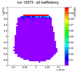 |
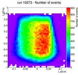
|
| 10374 | s0 & s2m (DVCS) | 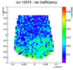 |
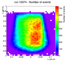
|
| 10376 | s0 & cer (DVCS) | 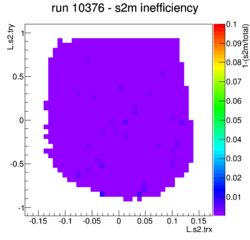 |
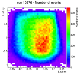
|