- Vic et al. finished a first draft for the EC layout, see: FAEC sw Module-plate-section 1 rev2.pdf (one section) and sw Module-plate-sections 1-2 rev2.pdf (two sections). XZ's comments: inner coverage not enough (?)
- Xiaochao's sketch of EC coverage for the PVDIS configuration: EC_radialcoverage_PVDIS_sketch.pdf
- Zhiwen sent out the latest magnet CAD model, see wiki/index.php/SoLID_Engineering_Integration_and_CAD#magnet. Ideally, we need to make CAD models of all EC components (preshower, shower, SPD) and fit the CAD models together to make sure there is no interference.
- 07/31/2018
- See main EC meeting discussion on 2018/07/31 for discussions of the module support design, produced by and tried out at SDU. We discussed what need to be modfied and Vic is working on changing the support design.
- Latest detector positioning and EC size by Zhiwen, see solid_layout_magnet_zwzhao_201702.pdf.
- Xiaochao's sketch for the SIDIS+J/Psi configuration: EC_radialcoverage_FAEC_sketch.pdf and EC_radialcoverage_LAEC_sketch.pdf.
- Next, Vic will design the supermodule (the 30-deg sector) layout for SIDIS+J/Psi configuration.
- Xiaochao will make a sketch for the PVDIS configuration.
- Vic's latest drawings: SOLID-Module-ver1.pdf (overall, schematic); SOLID-Module2-ver1.pdf (overall, schematic, longer rods); Super-Module-ver1.pdf (interactive 3D); Super-Module-3D-ver1.pdf (interactive 3D); Super-Module-ver1.jpg (some super-module drawing that I don't understand).
- Q/A on Vic's drawings:...
- How are the 4.76cm+1cm+7.49cm determined? Xiaochao calculated the total light loss due to bending vs. total spacing between the module back plate and the fiber connector, see her report at the EC 2016/4/21 meeting item E
- Xiaochao's list of items to discuss
- There has been two discussions on the SoLID general layout, on 3/27/17 and 2/20/17. Xiaochao's slides on space requirements of SPDs and ECals: SoLID_EC_20170220.pdf, and Zhiwen's 3/27 slides on detector arrangements: solid_layout_magnet_zwzhao_201702.pdf
- So far we have been giving 80cm total as the EC space requirement, and 6cm Z for LASPD, 4cm Z for FASPD. Are these sufficient? (also see PMT space requirement for LASPD below). Looking at Vic's latest drawing, the 80cm should include 5cm total for the preshower+lead+preshower support; 2cm of support in between preshower and shower (including module endplate); 44cm of shashlyk; 1cm of back endplate; 4.76cm+1cm+7.49cm of back support; and 10-14cm of room for routing the fiber behind the last support plate.
- LAEC needs shorter modules at both inner and outer radial sides. Outer radial short modules can be flush with other modules in the back (large Z). Inner radial modules can be flush with other modules in the front (small Z). I suppose these short modules can be supported from one-end only?
- Xiaochao's re-work of detector arrangements that includes radial coverage of each EC: TBD
- LASPD PMT needs space both in outer R and in Z (either smaller or larger Z). Can this be "puzzled-fit" with the LAEC?
- Paul suggested a reflective coating material called Vikuiti ESR film, see datasheet and a NIM paper by the POLAR experiment. Concerns: cost; may not gain much in light; will still need to wrap the module in black tape, etc.
- To do:
- Xiaochao should not forget to send fiber connectors to Paul.
- Jianping updated:
- Jay is making a new magnet map. Then will need to work with each detector group to see if the space and geometry is good enough. For ECal we will also involve the JLab engineering
- Timeline: want to submit the MIE in early March. Need some near-final information on the support to be in there.
- After the new year we want to involve
- We will continue the meeting next Monday.
- Latest design from Vic:
- did
- Latest design from Vic:
- did an analysis of the back plates if we were going to cantilever the modules. I applied the weight and bending moments of each module and restrained the plate only at the outer radius. The plate bends quite a bit but if I add a stiffening rib I can significantly reduce the bending, see the attached files. These are very rough models to understand the supports.
- Pictures showing bending of the support plane: MountingPlateFront-ver2.bmp and MountingPlateFront-ver1.jpg
- Questions to discuss:
- Do we still want to have independent super-modules that slide in on rails at the outer radius?
- Can we have instead on solid plate that is the full circle? Are ribs acceptable?
- Instead of using rails at the outer radius can we stack the super modules?
- We might have to go with a front plate to help eliminate the bending which is what we had in the design of a few years ago but then assembly becomes a little difficult.
- Here are drawings for prototyping the support structure: SOLID-1.pdf, SOLID-1-3.pdf, SOLID-1-4.pdf, SOLID-1-7.pdf, SOLID-1-8.pdf. However, we need to solve the warping problem first before prototyping any.
- Latest design from Vic:
- SOLID-Module-ver1.pdf (3D-view available in adobe); SOLID-Module-ver1.stp. Some "snapshots" are shown below (click on the image to see full-scale)
-
-

-


-
-
Participants: Vic Guarino, Xiaochao Zheng, Jianping Chen, Zhiwen Zhao, Paul Reimer
- We discussed the following topics today:
- module mechanical tests requested from Chinese groups: mech_test_module_20160407.pdf
- fiber bending loss calculation, see slides fiber_bending_20160414.pdf and spreadsheet shashlyk_fiber_bending_space_calc.xls
- update from EC group: light yield is lower than expected,
may have to use Tyvek after all (coeff of static friction close to 0.1).
-
Participants: Vic Guarino, Xiaochao Zheng, Jianping Chen, Zhiwen Zhao, Paul Reimer
- We discussed the following topics today:
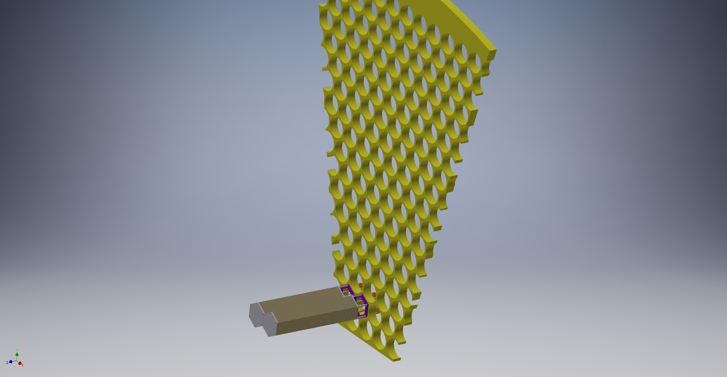
- We have converged the idea of using two support planes.
Backplane for cantilevering the shower modules, front support plane for
the preshowers.
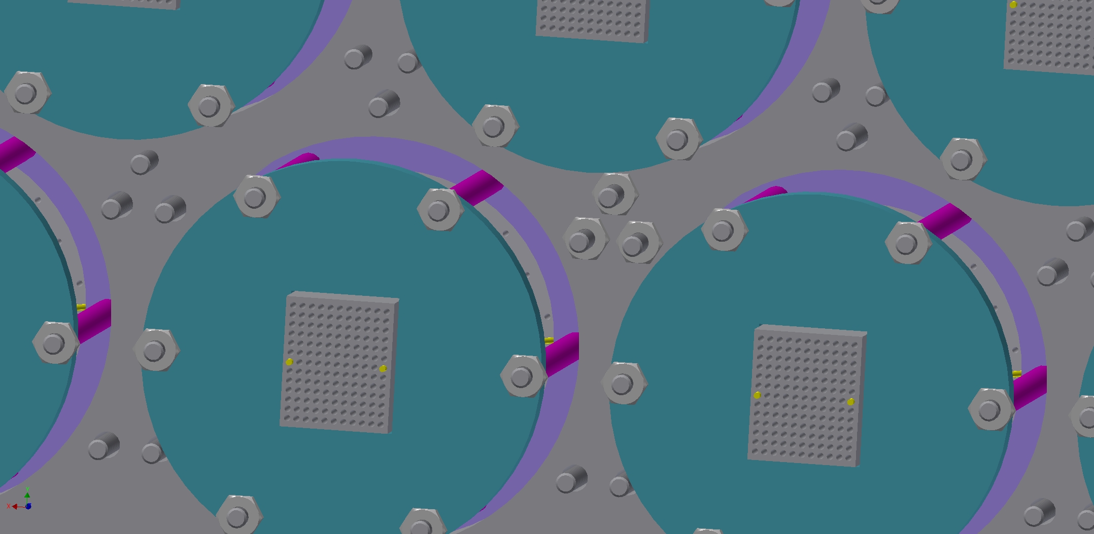
- The support planes will each cover 1/12 of the 2pi azimuthal region. There will be 3 shapes to accommodate the "zigzag" of the module's hexagon profile. The forward-angle will have one design. The back-angle (LAEC) of SIDIS will require another set of 12 planes
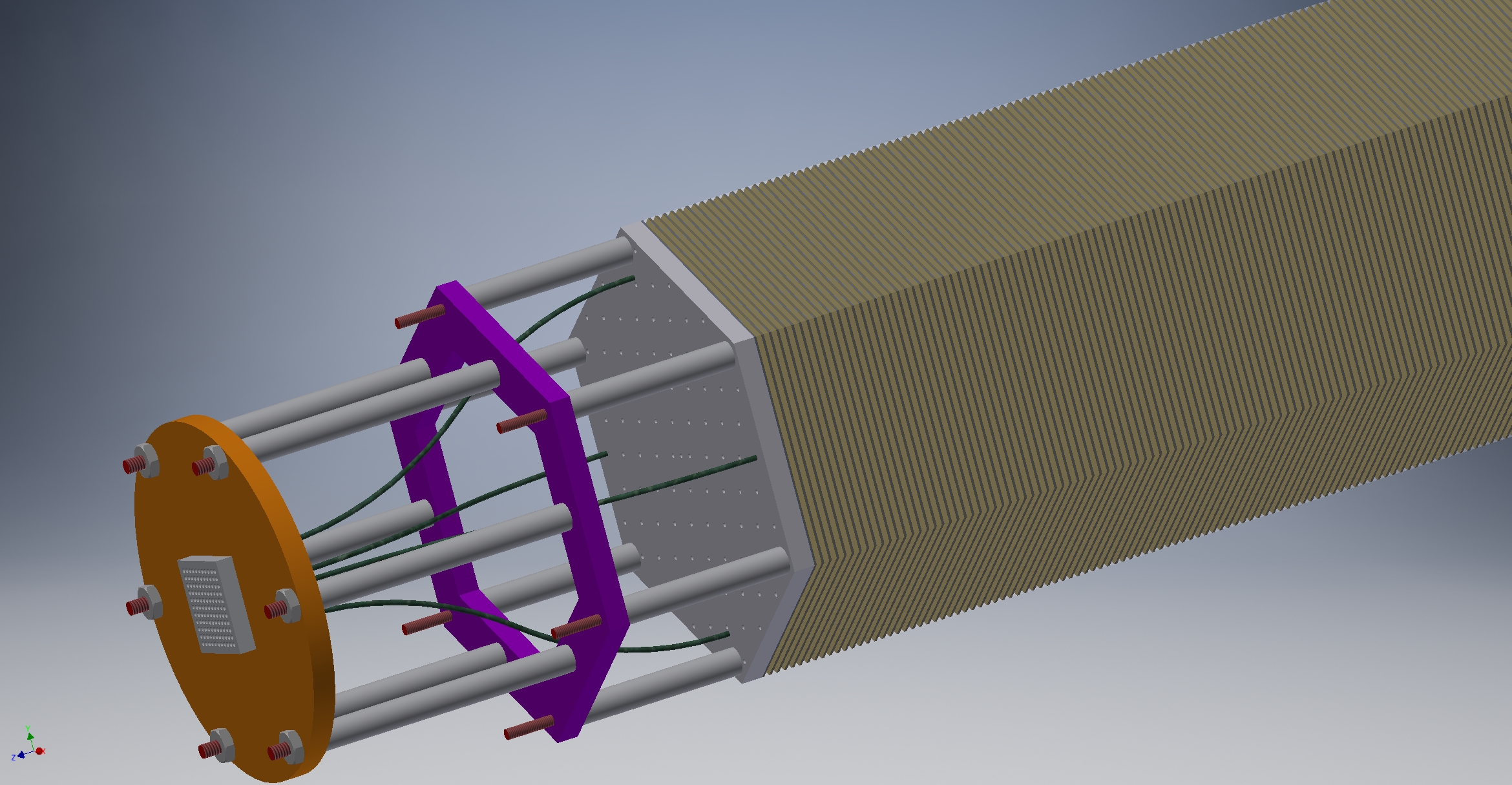
- To fix the shower modules to the back support plane, the six rods can be longer than the module, and fixed to the back support plane with nuts;
- There can be spacing between the module's back endplane
and the back support plane. Spacers will be used on the rods. The
spacing depends on the fiber bending radius and the size of the holes
on the back support plane. Xiaochao will calculate the spacing for
different senarios.
- Space will be needed after the back support plane to route/bend the clear fibers.
- The DDK connectors need to be fixed/mounted to the back support plane. Can consider mounting the adaptor to the support.
- Use
of module side planes: The only concern is
performance. There should be no difficulty from the support point of
view alone. Jianping noted the compression may change due to radiation.
The decision is thus TBD and also depends on stress calculation results.
- Preshower and shower modules should be detached. (not combined into one single module).
- Paul questioned the use of SiPMs and Xiaochao will confirm that it will be difficult to use.
- The use of the middle support plane is TBD, pending rod stress calculation.
- To dos:
- Vic will update the module stress calculation using a >2 safty factor and stainless steel rods. Vic mentioned the STAR Ecal was built 15 years ago, cantilevered, and there has been no problem with it.
- Xiaochao ordered some DDK connectors and will send samples to Paul/Vic;
- Xiaochao will look into collecting material for a mechanical prototype for use by Paul/Vic.
- Remaining topics to be discussed/determined later:
- material: anodized Al7075 for the endplates (and side plates), stainless steel 304L rods for the module?
-
Should Vic also do the SPD support design? -- pending Pauls' budget
situation. Jianping noted this can be done directly to the Preshower
support plane.
- We have not discussed the support for the lead plates in front of the preshowers.
- What is the tolerance on the module shape, including the length of the shower module, and the possible uneven height of each individual module? So far there is a 1cm difference between SDU and THU's prototypes (which we hope to resolve if all groups use the same vendor for the scintillator and the lead plates, and use the same reflective layers), and the SDU's prototype has uneven height of less than 1mm.
- Participants: Xiao Zheng, Vic Guarino (we had a mixup in the meeting arrangement and didn't have full participation.)
- To answer the service requirement question:
- In
general, if one module is broken then there is no
urgent need to fix it. But if 10 or 20 are broken in one 30-deg sector,
or if 5-6 are broken and areclustered together, then we probably should
fix them and the time available for fixing will be as needed (days? a
week?). Obviously we want to avoid such long down times. Paul's answer
is "once a year to take it apart".
- Fully switching between PVDIS and SIDIS is another issue and may take several months.
- We do want to keep some flexibility in the accessibility
of the preshowers. The preshowers will degrade faster than the shashlyk
module. It will be ideal if we can minimize the down time needed to
slide out the return steel, the ECal plane, and to access the preshower
from the front of the ECal.
- Vic will work more on the individual module
design, including how to integrate the fiber connectors to the module
endplate and how to mount the preshower individually to the shashlyk
module (maybe through a center hole to screw it on to the shashlyk end
plate?).
- updated calculation on the module cantilevering stress: Module-ver1.pdf
- followup item on the minimal bending diameter of the fibers: This has been measured in the ATLAS TDR, see Fig.5-24. Here, the light yield while the fiber was still wound with a certain diameter was measured and compared to the light yield before the bending stress (straight fiber). The fibers being tests were 1mm in diameter, same as ours. The Y11 from Kuraray shown was the multiclad, S-type, which is the best type and the ATLAS results on Y11 is consistent with the Kuraray specification with a light loss of <5% even at very small bending diameters. Obviously, the question about the bending diameter is a tradeoff between bending space and light loss. For now I think we should aim for 10cm bending diameter, and definitely do not go below 7cm.
- We will meet on Monday 3/14 because Vic will be at BNL next week.
- Participants: Victor Guarino, Paul Reimer, Zhiwen Zhao, Xiaochao Zheng; Jianping Chen (for 10 sec? only).
- Latested but probably outdated designs that we have on hand:
- Design of the Ecal support can be seen in this
file: ModuleAssembly2-1.pdf,
from Vic a couple of years ago. This design has two support planes to
hold the shashlyk modules, each plane has a "swiss-cheese" struture
with one hex- or circular hole per module. The module rods go through
the back plane only. Back plane has circular holes for fiber routing.
Modules "sit" in hex-shape holes in the front plane.
- This design does not have preshowers.
- Also
it's not clear how the plane integrates with the
endplates of the module because so far the endplates have the same size
as the module itself and thus does not allow spacing, while the
swiss-cheese support design needs a minimal amount of material to work.
This problem can be solved if we design the endplates of the module
along with the support plane.
- Adding the preshowers , Paul made a sketch: module support dimensions.pdf. But how to route the preshower fibers out needs to be determined (see preshower prototype pic).
- Design of how Ecal connects to the Solenoid can be seen here: from slide 10 of Whit's presentation at the Jan 2016 collaboration meeting: http://hallaweb.jlab.org/12GeV/SoLID/meeting_coll/2016_01/Whit_SoLID_JAN_2016-SEAY.pdf
- The latest design ideas:
- What Vic has in mind is to cantilever all modules from
the back plane only and eliminate the front plane. The advantage is
relatively easier access to the modules and thus services. Vic will
work on how to cantilever all modules (using the six rods integrated in
the module? Or only use 1 or 3 rods and the other rods are only part of
the module?...) -- but see followup on 3/16
- On the other hand, during the EC meeting discussions,
Jianping and Xiaochao are worried that the cantilevering stress on the
rods is too high and also it is not so reliable to rely on the high
compression/friction in the long term (Supporting weight by friction is
needed to minimize the rod deformation), and we talked about
- using six 1mm-thick anodized aluminum plates to support the module weight from the sides; AND
- shashlyk modules are supported from both front and back; -- but see followup on 3/16
- use three support planes, front is to support the preshower with the fibers coming out from the opposite side of the support; mid plane is to support the front of the shashlyk modules and can be made of carbon fiber; and back plane is to support the shashlyks and can be thick. However, from the discussion today, if we can integrate preshower with shashlyk module-by-module then we could use only two planes. Even so, the front plane complicates the preshower fiber routing and the service accessibility in general. -- but see followup on 3/16
- Todo:
- Zhiwen will ask Whit for any files he has that relate to
slide 10 of the Jan2016 report (see above), so Vic can start from
there. Questions we need to help Vic include:
- Where are the rails that the ECal support can grab on to? Do the Ecal slide in from the front or the back of the solenoid?
- Do we need to build supermodules?
- There are interferences in both R and z that need to be solved first.
- Also this drawing does not seem to include MRPC and SPD???
- What about LASPD of SIDIS and the PVDIS configuration?
- Zhiwen will ask each detector group to see if they have updated CAD files to upload.
- Vic will generate (may has already generated) CAD
drawings for the shashlyk module and see how to attach them to the
support plane. A new design for the module endplate that integrates
into the support hole is also needed.
- Xiaochao will update the Ecal group on the possible requirement of integrating preshower to the shashlyk modules (can't be done using the six rods of the shashlyk because of the high compression, but can possibly be done easily by screwing the preshower to the front endplate of the shashlyk using separate holes and thin rods), and the general idea of cantilevering and using only one (back) support plane. -- this is no longer necessary, see followup on 3/16
- We will continue the discussion about one plane vs. two next week.